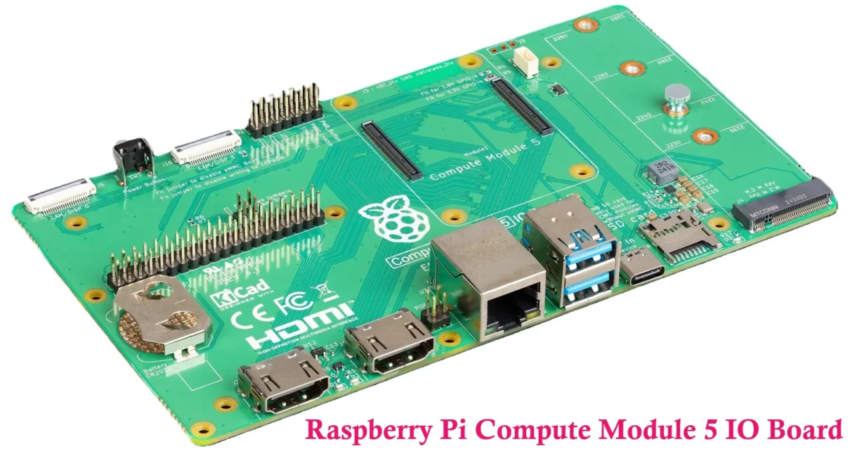
The Raspberry Pi Compute Module 5 (CM5) IO Board is the official development and evaluation platform for the Raspberry Pi Compute Module 5. Unlike a standard Raspberry Pi single-board computer, the CM5 is designed for embedded and commercial applications, where developers require full access to the module’s hardware interfaces before designing custom carrier boards.
Developed by the Raspberry Pi Foundation, the CM5 IO Board exposes nearly every interface available on the Compute Module 5, providing a ready-to-use platform for hardware evaluation, software development, peripheral testing, and rapid prototyping. Instead of designing a custom PCB during the early stages of development, engineers can install a Compute Module 5 on the IO Board and immediately begin working with interfaces such as PCIe, USB 3.0, Gigabit Ethernet, dual HDMI outputs, MIPI camera and display connectors, and the standard 40-pin GPIO header.
The board also serves as an official hardware reference, enabling developers to validate both hardware and software before transitioning to a production-ready carrier board. Because it follows Raspberry Pi’s reference design guidelines, it significantly reduces development time and design risk.
Designed for embedded engineers, robotics developers, industrial automation, IoT and Edge AI applications, product designers, research institutions, and advanced makers, the CM5 IO Board supports the entire Compute Module 5 family, including Lite and eMMC variants, multiple RAM configurations, and wireless or non-wireless models. This flexibility allows developers to prototype using the same hardware configuration intended for their final product.
Related Articles:
- Build a Powerful and Affordable Raspberry Pi Media Server
- Raspberry Pi Compute Module 5 (CM5) Explained
- Raspberry Pi 5 Pinout, specifications, Pricing A Complete Guide
- Raspberry Pi LED Brightness Controller
- How to Recover Files from Raspberry Pi Memory Card
- Datasheet of Raspberry Pi Compute Module 5 IO Board
- Water Quality Monitoring System: TDS Sensor + ESP32/Arduino
- Air Quality Monitoring System – ESP32 + Blynk IoT Project
Unlike the Raspberry Pi 5, which is designed as a general-purpose computer, the CM5 IO Board is purpose-built for embedded system development, offering comprehensive access to the Compute Module 5’s interfaces for professional prototyping, testing, and product development.
What is Raspberry Pi Compute Module 5 IO Board?
The Raspberry Pi Compute Module 5 IO Board is the official carrier and development board created specifically for evaluating the Raspberry Pi Compute Module 5. It provides all the essential connectors, power circuitry, expansion interfaces, and debugging features required to transform the compact Compute Module into a fully functional development platform.

Unlike traditional Raspberry Pi computers where the processor, memory, storage, and connectors are permanently integrated onto a single PCB, the Compute Module 5 separates the computing hardware from the carrier board. The CM5 itself contains the processor, RAM, storage, and wireless hardware, while the IO Board supplies the external connectors and supporting electronics needed during development.
Once the Compute Module 5 is installed on the board, developers gain immediate access to numerous interfaces without requiring additional adapter boards or complex wiring. This significantly reduces development time and allows engineers to begin testing applications immediately.
Official Development Platform
The CM5 IO Board is the official hardware platform recommended by Raspberry Pi for evaluating Compute Module 5. Because it is designed by the same engineering team that developed the CM5 itself, it follows all recommended electrical layouts, signal routing practices, power requirements, and interface implementations.
As a result, developers can use the IO Board as a reliable baseline when testing hardware functionality, operating systems, boot methods, peripheral compatibility, and software performance.
Designed for Evaluating Compute Module 5
Before investing time and money into a custom carrier board, engineers typically need to verify that the Compute Module meets the requirements of their project. The CM5 IO Board makes this process straightforward by exposing nearly every hardware interface available on the module.

Developers can evaluate features such as:
- USB 3.0 connectivity
- Dual HDMI display output
- Gigabit Ethernet networking
- PCIe expansion through the M.2 M-Key slot
- GPIO functionality
- Camera and display interfaces
- Power management
- Operating system compatibility
This allows hardware validation before committing to production hardware.
Ideal for Hardware Prototyping
One of the biggest advantages of the CM5 IO Board is its suitability for rapid hardware prototyping. Engineers can quickly connect sensors, storage devices, displays, cameras, networking equipment, and expansion modules without designing custom electronics.
This greatly shortens development cycles while allowing multiple hardware configurations to be tested before finalizing a product design.
Software Development Platform
The board is equally valuable for software engineers. Since it exposes almost every interface available on the Compute Module, developers can build, debug, and optimize embedded Linux applications using actual production hardware.
Typical software development tasks include:
- Installing Raspberry Pi OS or other Linux distributions
- Developing device drivers
- Testing GPIO applications
- Building industrial control software
- Developing robotics applications
- Evaluating AI and computer vision software
- Testing PCIe peripherals
Testing Before Designing Custom Hardware
Designing a production carrier board involves considerable engineering effort and manufacturing cost. Any hardware mistakes may require multiple PCB revisions, increasing both development time and expenses.
The CM5 IO Board minimizes this risk by providing a fully validated reference platform. Engineers can first verify that their software, peripherals, power requirements, and system architecture operate correctly before creating their own carrier board, reducing costly design errors later in the development process.
Why Does the Raspberry Pi Compute Module 5 IO Board Exist?
The Raspberry Pi Compute Module 5 is intended primarily for embedded products rather than direct end-user applications. Since the module itself contains only the computing hardware, developers require an external carrier board to provide power, connectors, expansion interfaces, and peripheral access.

The official Compute Module 5 IO Board was created to eliminate this initial hardware barrier and provide a complete development environment that allows engineers to begin working immediately.
Exposes Nearly Every Interface of the Compute Module 5
The Compute Module contains numerous high-speed interfaces that are not directly accessible without a carrier board. The IO Board exposes these interfaces through industry-standard connectors, allowing developers to evaluate virtually every hardware capability of the CM5.
This includes:
- USB 3.0
- USB 2.0
- Dual HDMI outputs
- Gigabit Ethernet
- 40-pin GPIO
- MIPI CSI camera interfaces
- MIPI DSI display interfaces
- PCIe through an M.2 M-Key connector
- Fan connector
- RTC battery connector
Eliminates the Need for an Immediate Custom PCB
Developing a custom carrier board during the early stages of a project can significantly delay product development. Engineers would otherwise need to design schematics, perform PCB layout, manufacture prototype boards, assemble components, and debug hardware before software development can even begin.
The official IO Board removes these steps by providing a ready-to-use hardware platform that functions immediately after installing the Compute Module.
Simplifies Hardware and Software Debugging
During embedded system development, many issues originate from custom hardware rather than the software itself. Using a known-good reference platform allows developers to separate hardware-related problems from software bugs.
This simplifies troubleshooting and helps engineers identify issues more efficiently during system development.
Enables Rapid Prototyping
The IO Board significantly accelerates product development by allowing engineers to connect cameras, displays, SSDs, sensors, network equipment, USB peripherals, and GPIO devices without building additional hardware.
Developers can evaluate multiple hardware configurations, benchmark system performance, and validate peripheral compatibility within hours instead of waiting weeks for custom PCB fabrication.
Provides an Official Reference Design
Perhaps the most valuable purpose of the CM5 IO Board is that it serves as Raspberry Pi’s official reference implementation for Compute Module 5 hardware. Engineers designing their own carrier boards can study its schematic, PCB layout techniques, power architecture, interface routing, and connector placement to create reliable production hardware that follows Raspberry Pi’s recommended design practices.
Development Board vs Carrier Board
The terms development board, carrier board, evaluation board, and production carrier board are often used interchangeably, but they serve different purposes during the lifecycle of an embedded product. Understanding these differences is important when working with the Raspberry Pi Compute Module 5 ecosystem.
Development Board
A development board is designed to help engineers quickly evaluate hardware features, write software, and prototype new applications. It typically includes numerous connectors, debugging interfaces, expansion headers, status LEDs, and documentation that simplify product development.
The Raspberry Pi Compute Module 5 IO Board is primarily a development board because its goal is to provide complete access to the CM5’s interfaces rather than optimize for compact size or production deployment.
Carrier Board
A carrier board is a PCB that hosts a Compute Module and provides the connectors, power supplies, and supporting circuitry required for a specific application. Carrier boards may be simple or highly customized depending on the intended product.
Unlike development boards, carrier boards often include only the interfaces required by the final application, reducing cost, size, and power consumption.
Evaluation Board
An evaluation board is intended for testing and validating a processor or embedded module before committing to a production design. It demonstrates hardware capabilities under real operating conditions and allows engineers to verify compatibility with peripherals, operating systems, and software stacks.
The Compute Module 5 IO Board also functions as an evaluation board because it enables comprehensive testing of all major CM5 features.
Production Carrier Board
A production carrier board is the custom hardware ultimately integrated into a commercial product. It contains only the interfaces, connectors, and components required by the finished device, resulting in lower manufacturing cost, smaller dimensions, improved reliability, and optimized power consumption.
Most embedded products based on the Raspberry Pi Compute Module eventually replace the official IO Board with a purpose-built production carrier board.
Development vs Carrier vs Evaluation vs Production Carrier Board
| Feature | Development Board | Carrier Board | Evaluation Board | Production Carrier Board |
|---|---|---|---|---|
| Primary Purpose | Development and prototyping | Host a Compute Module | Hardware evaluation and testing | Commercial product deployment |
| Typical Size | Large | Varies by application | Medium to Large | Optimized and compact |
| Cost | Higher | Moderate | Higher | Lowest for mass production |
| Expansion Interfaces | Extensive | Application dependent | Extensive | Only required interfaces |
| Production Suitability | No | Possible | No | Yes |
| Debug Features | Comprehensive | Limited | Comprehensive | Usually minimal |
| Typical Users | Developers and engineers | Embedded designers | Validation engineers | Manufacturers and OEMs |
In practice, the Raspberry Pi Compute Module 5 IO Board combines the functionality of a development board, evaluation board, and a fully featured carrier board. It enables developers to validate hardware, build software, prototype products, and understand Raspberry Pi’s official hardware design before creating a custom production carrier board tailored to their specific application.
Raspberry Pi Compute Module 5 IO Board Hardware Overview
The Raspberry Pi Compute Module 5 IO Board is a feature-rich development platform that exposes nearly all the interfaces available on the Raspberry Pi Compute Module 5 (CM5). It allows developers to evaluate hardware functionality, test peripherals, develop software, and prototype embedded systems without designing a custom carrier board.

Unlike the compact Raspberry Pi 5, the CM5 IO Board is intentionally larger to accommodate numerous connectors, expansion slots, debugging interfaces, and power circuitry. The board layout is designed to provide easy access to each interface, making it ideal for hardware development, testing, and educational purposes. The size of Compute Module 5 IO Board is approximately 160 mm × 90 mm.

After installing a compatible Compute Module 5, the IO Board transforms into a complete embedded development system capable of supporting storage devices, cameras, displays, networking equipment, GPIO peripherals, PCIe devices, and industrial expansion modules.
The official Compute Module 5 IO Board includes the following major hardware components and connectors:
- Compute Module 5 board-to-board connectors
- USB Type-C power input
- Two USB 3.0 Type-A ports
- Two full-size HDMI output ports
- Gigabit Ethernet (RJ45) connector
- 40-pin Raspberry Pi GPIO header
- M.2 M-Key PCIe expansion slot
- Dual MIPI CSI camera connectors
- Dual MIPI DSI display connectors
- RTC battery connector
- 4-pin PWM fan connector
- Debug UART interface
- Boot mode and recovery headers
- Status LEDs
- Power management circuitry

Together, these interfaces expose nearly every major hardware capability of the Compute Module 5, enabling engineers to evaluate complete embedded solutions before designing production hardware.
For easy identification of every connector and expansion interface, the following labeled diagram illustrates the major components of the Raspberry Pi Compute Module 5 IO Board.
Raspberry Pi Compute Module 5 IO Board Specifications
Unlike the Compute Module 5, which defines the processor, memory, and wireless capabilities, the IO Board specification focuses on the available connectors, expansion interfaces, power circuitry, and development features. The table below summarizes the key hardware specifications of the official Raspberry Pi Compute Module 5 IO Board.

| Specification | Description |
|---|---|
| Board Type | Official Raspberry Pi Compute Module 5 Development and Evaluation Board |
| Compatible Module | Raspberry Pi Compute Module 5 (All Variants) |
| Board Dimensions | Approximately 160 mm × 90 mm |
| Power Input | USB Type-C (5 V DC) |
| USB Ports | 2 × USB 3.0 Type-A |
| Display Outputs | 2 × Full-size HDMI |
| Ethernet | Gigabit Ethernet (RJ45) |
| GPIO | 40-pin Raspberry Pi compatible GPIO Header |
| PCIe Expansion | M.2 M-Key Slot (PCIe Gen2 x1) |
| Camera Interfaces | 2 × MIPI CSI Connectors |
| Display Interfaces | 2 × MIPI DSI Connectors |
| RTC Support | Dedicated RTC Battery Connector |
| Cooling | 4-pin PWM Fan Header |
| PoE Support | PoE+ Header for compatible PoE HAT |
| Debug Interfaces | UART Debug Header and Boot Mode Interface |
| Operating Systems | Raspberry Pi OS, Ubuntu, Debian, Yocto, Buildroot and other compatible Linux distributions |
| Primary Purpose | Development, Evaluation, Prototyping and Embedded Product Design |
The official IO Board provides developers with direct access to virtually every external interface required during embedded system development. Since it follows Raspberry Pi’s reference hardware design, engineers can confidently use it to evaluate software, peripherals, and system performance before creating a custom production carrier board.
Complete Port Walkthrough
One of the biggest advantages of the Raspberry Pi Compute Module 5 IO Board is the wide variety of built-in connectors and expansion interfaces. Each connector is designed to expose a specific capability of the Compute Module 5, allowing developers to evaluate every major subsystem without additional adapter boards.
The following sections explain the purpose, functionality, and common applications of each major connector available on the board.
USB Type-C Power Input
The USB Type-C connector serves as the primary power input for the Raspberry Pi Compute Module 5 IO Board. It supplies regulated power to both the development board and the installed Compute Module 5, ensuring stable operation during hardware evaluation and software development.
Unlike many USB Type-C ports found on laptops or smartphones, this connector is dedicated to power delivery and is not intended for high-speed USB data communication.
Supported Input Voltage
The IO Board is designed to operate from a standard 5 V DC USB Type-C power supply. The onboard power management circuitry distributes the required voltages to the Compute Module and all onboard peripherals.
Recommended Power Adapter
For reliable operation, Raspberry Pi recommends using a high-quality USB Type-C power supply capable of delivering sufficient current for both the Compute Module and connected peripherals.
A 5 V, 5 A USB Type-C power adapter is recommended, particularly when using:
- USB storage devices
- NVMe SSDs
- USB cameras
- Multiple USB peripherals
- PCIe expansion cards
Using an undersized power supply may result in undervoltage warnings, unstable operation, or unexpected system resets.
Current Capability
The total current available depends on the connected power adapter and the overall system load. Developers should account for the combined power consumption of:
- Compute Module 5
- USB devices
- HDMI displays
- PCIe devices
- Cooling fan
- GPIO peripherals
For demanding applications involving NVMe storage or AI accelerators, using the recommended power supply ensures stable performance under heavy workloads.
USB 3.0 Type-A Ports
The Compute Module 5 IO Board includes two USB 3.0 Type-A ports, providing high-speed connectivity for external peripherals. These ports are ideal for development tasks that require fast data transfer or connection of multiple USB devices.
High-Speed Data Transfer
Each USB 3.0 port supports data transfer rates of up to 5 Gbps, making them suitable for bandwidth-intensive applications such as:
- External SSDs
- USB flash drives
- Industrial cameras
- Machine vision devices
- USB capture cards
- AI accelerator modules
Compared to USB 2.0, USB 3.0 offers significantly higher throughput, reducing transfer times for large files and improving performance for high-speed peripherals.
USB Power Delivery
The USB ports also provide power to connected peripherals. However, the available current is shared with the entire system and ultimately depends on the external power supply connected to the USB Type-C input.
High-power devices such as external hard drives may require their own power source or a powered USB hub.
Compatible USB Devices
The USB 3.0 ports support a wide variety of peripherals, including:
- Keyboard and mouse
- USB flash drives
- External NVMe enclosures
- USB webcams
- Industrial USB cameras
- USB audio interfaces
- Wi-Fi adapters
- Bluetooth dongles
- USB Ethernet adapters
- Development tools and programmers
The ports are backward compatible with USB 2.0 and USB 1.1 devices, ensuring compatibility with both legacy and modern peripherals.
Dual Full-Size HDMI Outputs
The Raspberry Pi Compute Module 5 IO Board provides two full-size HDMI connectors, allowing developers to connect one or two external displays without requiring adapter cables. These outputs are especially useful for desktop environments, digital signage, industrial HMIs, and multi-monitor embedded systems.
Dual Display Support
Both HDMI connectors can operate simultaneously, enabling a true dual-display configuration. Users can either extend the desktop across two monitors or configure each display independently for different applications.
High-Resolution Video Output
The HDMI interfaces support high-resolution digital video output suitable for modern monitors and televisions. Depending on the Compute Module configuration and software support, resolutions up to 4K Ultra HD can be achieved, making the board suitable for graphics-intensive embedded applications.
Display Mirroring
Display mirroring allows both HDMI outputs to show identical content. This mode is useful for:
- Presentations
- Training systems
- Retail displays
- Digital signage
- Demonstration kiosks
Extended Desktop
In extended desktop mode, each HDMI monitor functions independently, increasing the available workspace for development and multitasking. This configuration is particularly beneficial for:
- Software development
- Industrial control systems
- Security monitoring
- Financial dashboards
- Control room applications
Gigabit Ethernet (RJ45)
The onboard Gigabit Ethernet interface provides reliable wired networking for embedded applications requiring high-speed communication, low latency, and dependable connectivity. For many industrial and commercial systems, Ethernet remains the preferred networking interface due to its stability and predictable performance.
Gigabit Ethernet PHY
The Ethernet subsystem uses a dedicated Gigabit Ethernet PHY (Physical Layer Transceiver) to convert digital Ethernet signals from the Compute Module into standard network signals transmitted through the RJ45 connector.
This enables network speeds of up to 1000 Mbps (1 Gbps), making the board suitable for applications involving large data transfers, network storage, industrial communication, and remote system management.
Network Boot Support
The Compute Module 5 supports booting over the network, allowing operating systems and boot files to be loaded from a remote server instead of local storage. This simplifies deployment and maintenance of multiple embedded systems in enterprise and industrial environments.
PXE and Remote Deployment
For compatible software configurations, developers can implement network-based boot and provisioning workflows similar to PXE (Preboot Execution Environment). This enables centralized operating system deployment, software updates, and remote management for large-scale embedded installations.
PoE Support
The IO Board includes a dedicated PoE+ header for use with compatible Power over Ethernet accessories. When combined with an appropriate PoE solution, both electrical power and network connectivity can be delivered through a single Ethernet cable, reducing cable clutter and simplifying installations in locations where dedicated power outlets are unavailable.
PoE support is particularly valuable in applications such as:
- Industrial automation
- Smart surveillance systems
- Remote monitoring stations
- Digital signage
- IoT gateways
- Factory automation
The combination of Gigabit Ethernet, network boot capabilities, and optional PoE support makes the Raspberry Pi Compute Module 5 IO Board a powerful platform for professional embedded networking applications.
40-pin GPIO Header
The Raspberry Pi Compute Module 5 IO Board includes a standard 40-pin General Purpose Input/Output (GPIO) header, offering compatibility with the familiar Raspberry Pi GPIO layout. This allows developers to interface the Compute Module 5 with a wide range of sensors, actuators, communication modules, and custom electronic circuits while maintaining compatibility with existing Raspberry Pi hardware and software.
Since the GPIO header follows the standard Raspberry Pi pinout, developers can easily migrate existing projects from Raspberry Pi boards to the Compute Module 5 platform with minimal hardware or software modifications.
GPIO Pin Compatibility
The 40-pin header exposes numerous programmable GPIO pins along with dedicated power and communication pins. It provides access to:
- 3.3 V power output
- 5 V power output
- Ground (GND) connections
- General-purpose digital input/output pins
- Hardware communication interfaces
The GPIO operates at 3.3 V logic levels. Applying voltages higher than 3.3 V directly to GPIO pins may permanently damage the Compute Module.
Raspberry Pi HAT Compatibility
The standard GPIO header enables compatibility with many Raspberry Pi HATs (Hardware Attached on Top) and expansion boards. Although physical compatibility depends on the IO Board’s larger form factor, electrically many HATs and GPIO expansion modules function normally.
Examples include:
- Relay boards
- Motor driver HATs
- Sensor expansion boards
- LCD and OLED displays
- ADC and DAC modules
- Industrial I/O interfaces
- CAN Bus and RS-485 modules
SPI (Serial Peripheral Interface)
The GPIO header provides hardware SPI interfaces for high-speed communication with external peripherals such as:
- Flash memory
- Display controllers
- Touchscreen controllers
- Analog-to-Digital Converters (ADCs)
- Digital-to-Analog Converters (DACs)
SPI offers full-duplex communication with relatively high data transfer rates, making it suitable for real-time embedded applications.
I²C (Inter-Integrated Circuit)
Multiple I²C interfaces are available for connecting low-speed peripherals using only two communication lines (SDA and SCL). I²C devices commonly connected include:
- Temperature sensors
- Pressure sensors
- EEPROM memory
- Real-Time Clock modules
- GPIO expanders
- Environmental sensors
UART (Universal Asynchronous Receiver-Transmitter)
Hardware UART pins provide reliable serial communication with external microcontrollers, industrial equipment, GPS modules, Bluetooth modules, and debugging consoles. UART remains one of the most widely used interfaces in embedded system development.
PWM (Pulse Width Modulation)
The GPIO header also supports hardware PWM outputs that can be used for:
- Servo motor control
- LED brightness control
- DC motor speed regulation
- Fan speed control
- Audio signal generation
The versatile GPIO interface makes the CM5 IO Board suitable for robotics, industrial automation, IoT devices, and embedded control systems.
M.2 M-Key PCIe Expansion Slot
One of the most significant improvements offered by the Raspberry Pi Compute Module 5 IO Board is the inclusion of a built-in M.2 M-Key expansion slot. Unlike the Raspberry Pi 5, which typically requires an additional PCIe HAT or adapter board, the official CM5 IO Board provides direct PCIe expansion through a dedicated M.2 connector, simplifying hardware development and reducing overall system complexity.
The M.2 slot enables developers to connect high-performance PCI Express peripherals directly to the Compute Module, making the board suitable for storage-intensive, networking, and AI-based applications.
PCIe Gen2 x1 Interface
The M.2 connector is connected to the Compute Module through a PCI Express Gen2 x1 interface, providing significantly higher bandwidth than USB-based expansion devices. Although it uses a single PCIe lane, it delivers ample performance for many embedded applications.
NVMe SSD Support
One of the most common uses of the M.2 slot is connecting an NVMe Solid-State Drive (SSD). Compared with traditional microSD cards, NVMe SSDs offer:
- Much faster boot times
- Higher sequential read/write speeds
- Improved random access performance
- Greater storage capacity
- Enhanced reliability for continuous operation
Using an NVMe SSD is particularly beneficial for embedded servers, AI workloads, industrial PCs, and data logging applications.
AI Accelerators
The PCIe interface also supports compatible AI accelerator modules that significantly improve machine learning inference performance while reducing CPU workload.
Typical AI accelerator applications include:
- Object detection
- Image classification
- Facial recognition
- Industrial machine vision
- Edge AI inference
High-Speed Network Adapters
The M.2 slot can also accommodate compatible networking devices, enabling specialized communication interfaces such as additional Ethernet controllers, wireless networking modules, or industrial communication hardware depending on software and driver support.
Video Capture and Multimedia Devices
PCIe expansion allows integration of compatible multimedia devices including video capture hardware and specialized processing cards for machine vision, industrial imaging, and multimedia applications.
No Additional PCIe HAT Required
A major advantage of the CM5 IO Board is that the PCIe interface is already routed to an onboard M.2 M-Key connector. Developers can install supported PCIe devices directly without purchasing separate PCIe adapter HATs, making hardware evaluation much simpler and more reliable.
MIPI CSI Camera Connectors
The Raspberry Pi Compute Module 5 IO Board provides dedicated MIPI CSI (Camera Serial Interface) connectors that enable direct connection of compatible camera modules for computer vision, image processing, surveillance, robotics, and AI applications.
Camera Module Support
The CSI connectors support official Raspberry Pi camera modules as well as compatible third-party MIPI CSI cameras designed for embedded vision applications.
Common applications include:
- Machine vision
- Industrial inspection
- Autonomous robots
- Smart surveillance
- Image recognition
- Scientific imaging
Multiple Camera Support
The IO Board provides dual MIPI CSI connectors, allowing developers to connect multiple cameras depending on the selected Compute Module configuration and software support. This enables stereo vision, multi-angle imaging, and simultaneous image acquisition for advanced embedded applications.
High-Speed CSI Lanes
The MIPI CSI interface uses dedicated high-speed differential lanes specifically designed for transferring uncompressed image data efficiently from image sensors to the Compute Module. Compared to USB cameras, MIPI CSI typically offers lower latency, reduced CPU overhead, and improved image quality.
MIPI DSI Display Connectors
The Compute Module 5 IO Board also includes dedicated MIPI DSI (Display Serial Interface) connectors for directly interfacing compatible LCD and touchscreen displays. MIPI DSI is widely used in embedded systems because it provides high-resolution display output with excellent signal integrity and low power consumption.
Official Raspberry Pi Displays
The DSI connectors support compatible official Raspberry Pi display modules, making them suitable for touchscreen interfaces, graphical user interfaces, and interactive embedded systems.
Industrial LCD Panels
In addition to official displays, many industrial-grade LCD panels utilizing the MIPI DSI interface can also be integrated into embedded products, allowing developers to build custom Human Machine Interfaces (HMIs), kiosks, industrial controllers, and medical devices.
Compared with HDMI displays, MIPI DSI provides a more compact internal display connection and is particularly well suited for permanently integrated embedded systems.
RTC Battery Connector
The Compute Module 5 IO Board includes a dedicated connector for attaching a Real-Time Clock (RTC) backup battery. This feature allows the onboard RTC to continue tracking time even when the primary system power is disconnected.
Real-Time Clock (RTC)
An RTC is responsible for maintaining accurate date and time information independently of the operating system. It is especially useful in embedded systems that may not always have access to an Internet time server.
Battery Backup
Connecting a compatible RTC battery ensures that timekeeping continues during power outages or when the system is completely powered off. Once power is restored, the system can immediately retrieve the correct time without requiring network synchronization.
Applications
Maintaining accurate system time is important for:
- Industrial automation
- Data logging
- Security systems
- Access control
- Medical equipment
- IoT gateways
- Embedded servers
4-pin PWM Fan Connector
To support continuous high-performance operation, the Raspberry Pi Compute Module 5 IO Board includes a dedicated 4-pin PWM fan header. It enables automatic cooling of the Compute Module when running processor-intensive workloads.
PWM Fan Control
The PWM (Pulse Width Modulation) control signal allows software or firmware to dynamically adjust the fan speed according to processor temperature. During light workloads, the fan can operate at reduced speed or remain off, minimizing both power consumption and acoustic noise.
Tachometer Feedback
The fourth pin provides a tachometer signal that allows the operating system to monitor the fan’s rotational speed (RPM). This helps detect fan failures and ensures reliable thermal management.
Thermal Management
Active cooling is particularly beneficial when using:
- NVMe SSDs
- AI accelerator modules
- Industrial workloads
- Continuous video processing
- Machine learning inference
- Long-duration computational tasks
Maintaining lower operating temperatures helps improve system stability and sustain maximum processing performance.
Debug Interfaces
The official Raspberry Pi Compute Module 5 IO Board incorporates dedicated debugging interfaces that simplify software development, hardware troubleshooting, and system recovery. These interfaces are especially valuable during firmware development and custom carrier board design.
UART Debug Console
A hardware UART interface provides low-level serial communication directly with the Compute Module. Developers can monitor boot messages, diagnose kernel issues, access command-line interfaces, and troubleshoot operating system startup even when HDMI output is unavailable.
Boot Mode Selection
The IO Board includes hardware provisions for selecting different boot modes during development. These options allow engineers to test various boot sources, perform firmware updates, and validate storage configurations before deploying production hardware.
Recovery and Programming
Recovery interfaces simplify restoring corrupted software images, flashing firmware, and reprogramming compatible Compute Module variants. These features are particularly useful during early hardware bring-up, software testing, and production validation.
Together, the UART console, boot configuration options, and recovery interfaces provide developers with comprehensive debugging capabilities, making the Raspberry Pi Compute Module 5 IO Board an effective platform for embedded Linux development, hardware validation, and custom product design.
Power Architecture of Raspberry Pi Compute Module 5 IO Board
A reliable power distribution system is one of the most critical aspects of any embedded development platform. The Raspberry Pi Compute Module 5 IO Board incorporates a carefully designed power architecture that provides stable, regulated power to the Compute Module as well as all onboard peripherals and expansion interfaces. This reference implementation allows developers to evaluate real-world power behavior before designing their own production carrier boards.
Unlike custom carrier boards that require developers to design complex power sequencing and voltage regulation circuits, the official CM5 IO Board already includes the necessary power management circuitry. This significantly reduces development complexity while ensuring that the Compute Module operates according to Raspberry Pi’s recommended hardware design guidelines.
USB Type-C Power Input
The primary power source for the Compute Module 5 IO Board is the onboard USB Type-C connector. It accepts a regulated 5 V DC input and distributes power throughout the board using dedicated voltage regulators and power management circuitry.
The USB Type-C connector supplies power to:
- Compute Module 5
- USB 3.0 ports
- HDMI interfaces
- Ethernet controller
- M.2 PCIe slot
- GPIO expansion header
- Cooling fan header
- Camera and display interfaces
Using a high-quality power adapter helps maintain stable operation, especially when multiple high-power peripherals are connected simultaneously.
Power Management Integrated Circuit (PMIC)
The IO Board works together with the Compute Module’s onboard Power Management Integrated Circuit (PMIC) to generate and regulate the various supply voltages required by the processor, memory, storage, and peripheral interfaces.
The PMIC performs several important functions:
- Voltage regulation
- Power sequencing
- Power monitoring
- Over-current protection
- Under-voltage detection
- System startup management
This intelligent power management ensures reliable system operation while protecting sensitive electronic components from abnormal operating conditions.
Multiple Voltage Rails
Although only a single 5 V input is supplied externally, the board internally distributes multiple regulated voltage rails required by different subsystems.
Typical voltage rails include:
- 5 V for USB peripherals and onboard circuitry
- 3.3 V for GPIO and digital interfaces
- Lower core voltages for the processor and memory
- Dedicated supplies for high-speed interfaces
Each voltage rail is carefully regulated to minimize electrical noise and provide stable operation for high-speed digital interfaces such as PCI Express, HDMI, USB 3.0, and Gigabit Ethernet.
Power Sequencing
Modern System-on-Chip (SoC) devices require their supply voltages to be enabled in a specific sequence during power-up and power-down. Incorrect sequencing may prevent the processor from booting or even damage sensitive components.
The official CM5 IO Board implements the recommended power sequencing specified by Raspberry Pi, ensuring that every subsystem is initialized in the correct order. This allows developers to evaluate hardware without worrying about low-level power sequencing issues.
USB Power Limits
All USB peripherals connected to the board share the available power supplied through the USB Type-C input. Devices with high power consumption such as external hard drives, NVMe SSDs in USB enclosures, AI accelerators, and industrial USB cameras can significantly increase the overall system power requirement.
For systems using multiple peripherals, Raspberry Pi recommends using a high-current USB Type-C power supply capable of delivering sufficient power under maximum load. If the available current is exceeded, the system may display undervoltage warnings or experience unstable operation.
When designing custom carrier boards, engineers should carefully calculate the total system power budget by considering the Compute Module, USB devices, PCIe peripherals, displays, cameras, cooling fans, and any external GPIO circuitry.
PCIe Expansion on Raspberry Pi Compute Module 5 IO Board
One of the standout features of the Raspberry Pi Compute Module 5 IO Board is its built-in PCI Express expansion capability. Unlike many single-board computers that require external adapter boards, the official IO Board integrates an M.2 M-Key connector, allowing developers to connect high-speed PCIe peripherals directly to the Compute Module.
This makes the board considerably more versatile for embedded applications that require fast storage, AI acceleration, advanced networking, or specialized expansion hardware.
PCIe Gen2 x1 Interface
The onboard M.2 connector is connected through a PCI Express Gen2 x1 interface. Although it uses a single PCIe lane, it provides significantly higher bandwidth than USB-based expansion devices and is well suited for many embedded computing applications.
Direct PCIe connectivity also reduces protocol overhead, resulting in lower latency and improved performance for supported devices.
NVMe Solid-State Drives
Installing an NVMe SSD is one of the most popular uses of the M.2 slot. Compared with booting from a microSD card, NVMe storage provides:
- Faster operating system boot times
- Higher read and write performance
- Reduced application loading times
- Greater reliability for continuous operation
- Larger storage capacities
For industrial computers, edge servers, and AI systems, NVMe storage significantly improves overall system responsiveness.
AI Accelerator Modules
Edge Artificial Intelligence applications often require hardware acceleration beyond the capabilities of the CPU alone. The PCIe interface enables the use of compatible AI accelerator modules that can dramatically increase machine learning inference performance while reducing processor utilization.
Typical AI applications include:
- Object detection
- Image classification
- Facial recognition
- Industrial quality inspection
- Autonomous robotics
- Computer vision
Google Coral TPU and Similar Accelerators
The PCIe interface also enables support for compatible AI inference hardware such as the Google Coral TPU and other machine learning accelerator modules, subject to hardware compatibility and software driver support. These dedicated processors significantly improve inference speed while consuming much less power than CPU-based processing.
Networking Expansion
Besides storage devices, the PCIe slot can accommodate compatible networking hardware including additional Ethernet adapters, wireless communication modules, and specialized industrial communication interfaces. This flexibility allows developers to build networking solutions tailored to their specific applications.
High-Speed Storage and Embedded Applications
The combination of PCIe expansion and Compute Module 5 processing power makes the IO Board suitable for numerous storage-intensive applications, including:
- Edge data logging
- Industrial gateways
- Embedded file servers
- Video recording systems
- Network Attached Storage (NAS)
- Machine vision systems
- AI edge computing devices
By integrating the M.2 connector directly onto the development board, Raspberry Pi provides a convenient platform for evaluating PCIe devices before incorporating them into a custom carrier board design.
Camera and Display Connectivity
The Raspberry Pi Compute Module 5 IO Board is designed for applications requiring advanced imaging and display capabilities. It includes dedicated MIPI CSI camera connectors and MIPI DSI display connectors, enabling developers to build embedded vision systems, industrial Human Machine Interfaces (HMIs), robotics platforms, and multimedia applications.
Since these interfaces connect directly to the Compute Module through high-speed MIPI lanes, they offer lower latency and higher performance than equivalent USB-based peripherals.
Dual Camera Connectivity
The board provides two MIPI CSI connectors, allowing developers to interface compatible Raspberry Pi camera modules and third-party MIPI cameras. Depending on software configuration and application requirements, the dual-camera setup can support:
- Stereo vision systems
- Front and rear camera configurations
- Machine vision applications
- Industrial inspection systems
- AI image processing
- Security and surveillance solutions
The MIPI CSI interface transfers high-resolution image data directly to the processor with minimal CPU overhead, making it suitable for demanding real-time vision applications.
Dual Display Connectivity
In addition to dual HDMI outputs, the IO Board also includes two dedicated MIPI DSI connectors for connecting compatible LCD panels and touchscreen displays.
MIPI DSI displays are commonly used in:
- Industrial control panels
- Medical equipment
- Smart kiosks
- Portable embedded devices
- Robotics interfaces
- Human Machine Interfaces (HMIs)
Compared with HDMI displays, MIPI DSI panels provide a compact internal connection that is ideal for permanently integrated embedded products.
Flexible Camera and Display Configurations
The official IO Board allows developers to evaluate different combinations of camera and display interfaces according to the requirements of their embedded application. Typical configurations include:
| Application | Typical Configuration |
|---|---|
| Industrial HMI | 1 × DSI Display + HDMI Monitor |
| Machine Vision | 2 × CSI Cameras + HDMI Display |
| AI Edge Computing | CSI Camera + HDMI Monitor + NVMe SSD |
| Digital Signage | Dual HDMI Displays |
| Robotics | CSI Camera + DSI Touchscreen |
| Smart Kiosk | DSI Touch Display + CSI Camera |
| Surveillance System | Dual CSI Cameras + Ethernet Network |
Choosing the Right Display Interface
Both HDMI and MIPI DSI outputs serve different purposes. HDMI is generally preferred for external monitors, desktop displays, televisions, and development workstations, while MIPI DSI is better suited for compact embedded displays integrated directly into the final product.
Similarly, MIPI CSI cameras provide lower latency and higher performance than USB cameras, making them the preferred choice for embedded vision, robotics, and AI-based image processing applications.
The combination of dual HDMI outputs, dual MIPI DSI connectors, dual MIPI CSI interfaces, and PCIe expansion gives the Raspberry Pi Compute Module 5 IO Board exceptional flexibility for developing modern embedded systems that require high-speed imaging, graphics, and multimedia capabilities.
Using the Raspberry Pi Compute Module 5 IO Board
One of the primary advantages of the Raspberry Pi Compute Module 5 IO Board is that it allows developers to begin working with the Compute Module 5 immediately without designing a custom carrier board. After installing the Compute Module and connecting the required peripherals, the board operates much like a complete Raspberry Pi development platform while exposing additional interfaces intended for embedded product development.

The following steps outline a typical setup procedure for evaluating the Compute Module 5 on the official IO Board.
Step 1: Install the Compute Module 5
Begin by carefully mounting the Raspberry Pi Compute Module 5 onto the two high-density board-to-board connectors provided on the IO Board. Ensure the module is correctly aligned before applying gentle, even pressure until it is fully seated.
Improper installation may damage the connectors or prevent the system from booting correctly.
Step 2: Prepare the Boot Storage
The boot process depends on the type of Compute Module being used.
- CM5 Lite Models: Boot from an external microSD card or another supported storage device.
- CM5 eMMC Models: Boot directly from the onboard eMMC flash memory after flashing Raspberry Pi OS or another supported operating system.
Before powering the system, ensure the operating system image has been written to the selected storage device.
Step 3: Connect a Display
Connect an external monitor using one of the full-size HDMI ports. If required, both HDMI outputs may be connected simultaneously to enable a dual-monitor configuration.
For embedded applications, developers may alternatively use one of the onboard MIPI DSI connectors to interface a compatible LCD display.
Step 4: Connect USB Peripherals
Attach a USB keyboard and mouse to the onboard USB 3.0 Type-A ports. These peripherals allow direct interaction with the operating system during installation, configuration, and software development.
Additional USB devices such as storage drives, webcams, or development tools can also be connected as needed.
Step 5: Connect Ethernet (Optional)
If network access is required, connect a standard Ethernet cable to the Gigabit Ethernet port. A wired network connection provides:
- Internet connectivity
- Software package installation
- SSH remote access
- File transfer
- Network boot support
- Remote debugging
Although some Compute Module variants include onboard wireless networking, Ethernet generally provides greater stability and higher bandwidth for development work.
Step 6: Connect the Power Supply
Power the IO Board using a regulated 5 V USB Type-C power adapter. A high-quality power supply capable of delivering sufficient current is recommended, especially when using NVMe SSDs, USB peripherals, AI accelerators, or multiple displays.
After power is applied, the onboard status LEDs indicate system activity during the boot process.
Step 7: Boot Raspberry Pi OS
Once the Compute Module powers on, the firmware initializes the hardware and loads the installed operating system. If Raspberry Pi OS has been correctly installed, the familiar desktop environment or command-line interface will appear depending on the selected image.
Developers can now begin:
- Installing software packages
- Testing GPIO interfaces
- Connecting cameras and displays
- Evaluating PCIe devices
- Developing embedded applications
- Debugging hardware and software
With the Compute Module installed and the operating system running, the IO Board provides a complete development environment for evaluating nearly every feature of the Raspberry Pi Compute Module 5.

Software Support
The Raspberry Pi Compute Module 5 IO Board supports a wide range of operating systems and embedded Linux distributions. Because the board follows Raspberry Pi’s official hardware reference design, most supported operating systems work with minimal configuration, making software development considerably easier.
Raspberry Pi OS
Raspberry Pi OS is the officially recommended operating system for the Compute Module 5 IO Board. It offers the best hardware compatibility, long-term software support, and access to the complete Raspberry Pi software ecosystem.
It includes:
- Desktop and Lite editions
- Optimized Linux kernel
- GPIO libraries
- Camera support
- Display support
- Package management through APT
- Official firmware updates
Ubuntu
Ubuntu provides an excellent platform for developers building cloud-connected applications, edge AI systems, robotics, and enterprise Linux solutions. Ubuntu supports the Compute Module 5 while offering access to thousands of software packages and development tools.
Debian
Since Raspberry Pi OS is based on Debian, developers can also deploy Debian for projects requiring a more standard Linux environment. Debian is widely used in embedded computing because of its stability and extensive package repository.
Yocto Project
The Yocto Project enables developers to build highly customized embedded Linux distributions tailored to specific hardware requirements. It is commonly used in commercial embedded products where only the required software components are included.
Yocto is particularly popular in:
- Industrial automation
- Medical devices
- Networking equipment
- Automotive electronics
- Commercial embedded systems
Buildroot
Buildroot is another lightweight embedded Linux build system that generates compact operating system images with fast build times. It is suitable for resource-efficient embedded products where simplicity and minimal storage usage are priorities.
Device Tree Support
Like other Raspberry Pi platforms, the Compute Module 5 uses the Linux Device Tree to describe hardware configuration. Device Tree files allow developers to enable or disable peripherals, configure GPIO pins, define hardware overlays, and support custom carrier board designs without modifying the Linux kernel.
This flexibility greatly simplifies software migration from the official IO Board to a custom production carrier board.
Advantages of Raspberry Pi Compute Module 5 IO Board
The official Compute Module 5 IO Board provides numerous advantages over designing a custom carrier board during the early stages of product development. It offers a complete reference platform with comprehensive hardware access, enabling faster evaluation and significantly reducing engineering effort.
- Official Raspberry Pi Reference Platform: Designed and validated by Raspberry Pi, ensuring excellent hardware compatibility and reliable operation.
- Complete Interface Access: Nearly every interface available on the Compute Module 5 is exposed through standard connectors for easy evaluation.
- Integrated M.2 PCIe Expansion: The onboard M.2 M-Key slot allows direct connection of NVMe SSDs and PCIe peripherals without requiring additional adapter HATs.
- Dual Full-Size HDMI Outputs: Supports dual-monitor operation for development, industrial control, and multimedia applications.
- High-Speed USB 3.0 Connectivity: Enables fast communication with storage devices, cameras, and other USB peripherals.
- Comprehensive Debugging Features: UART, recovery interfaces, boot configuration, and status indicators simplify software and hardware troubleshooting.
- Accelerated Hardware Development: Developers can begin testing immediately without waiting for custom PCB fabrication.
- Excellent Documentation: Raspberry Pi provides extensive hardware documentation, schematics, design files, and software resources.
- Reliable Power Architecture: Official power sequencing and voltage regulation improve development stability and reduce hardware-related issues.
- Easier Software Bring-up: Since the hardware is already validated, developers can focus primarily on software development before migrating to a production carrier board.
Limitations of Raspberry Pi Compute Module 5 IO Board
Although the Compute Module 5 IO Board is an excellent development platform, it is not intended to replace a production carrier board or a general-purpose desktop computer. Understanding its limitations helps developers choose the right hardware for their specific application.
- Large PCB Size: The board is significantly larger than a Raspberry Pi 5 because it is designed for development rather than compact embedded products.
- No Protective Enclosure: The official board is supplied as an open PCB and typically requires an external enclosure if used outside a laboratory or development environment.
- Compute Module Purchased Separately: The IO Board does not include a Compute Module 5, so both products must be purchased independently.
- Higher Overall Cost: Purchasing the IO Board together with a Compute Module generally costs more than buying a Raspberry Pi 5.
- Not Intended as a Desktop Computer: Although it can run a desktop operating system, the board is primarily designed for embedded hardware development and evaluation.
- Wireless Depends on the Installed Module: Wi-Fi and Bluetooth are available only when using a Compute Module 5 variant that includes wireless connectivity.
- Single PCIe Lane: The onboard M.2 connector uses a PCIe Gen2 x1 interface, which is sufficient for many applications but offers less bandwidth than multi-lane PCIe systems.
Typical Applications of Raspberry Pi Compute Module 5 IO Board
The Compute Module 5 IO Board is widely used across research, industrial, and commercial environments because it provides immediate access to all major hardware interfaces. Before designing a production carrier board, developers commonly use the IO Board to evaluate hardware performance, validate software, and prototype complete embedded systems.
| Application Area | Typical Use |
|---|---|
| Robotics | Robot controllers, autonomous navigation, sensor integration, and motor control systems. |
| Machine Vision | Industrial inspection, barcode readers, quality control, and image processing using MIPI CSI cameras. |
| AI Edge Computing | Object detection, facial recognition, edge inference, and computer vision with PCIe AI accelerators. |
| Industrial Automation | Factory controllers, PLC replacements, monitoring systems, and industrial communication gateways. |
| IoT Gateways | Protocol conversion, edge data processing, sensor aggregation, and cloud connectivity. |
| Digital Signage | Dual-display advertising systems, information kiosks, menu boards, and multimedia displays. |
| Medical Devices | Diagnostic equipment, medical imaging, patient monitoring, and embedded healthcare systems. |
| Factory Control | Production monitoring, machine control, predictive maintenance, and equipment supervision. |
| Smart Kiosks | Self-service terminals, ticketing machines, interactive displays, and payment systems. |
| Embedded Linux Development | Kernel development, driver testing, custom operating systems, and carrier board validation. |
Thanks to its comprehensive hardware interfaces, official documentation, and proven reference design, the Raspberry Pi Compute Module 5 IO Board is an excellent platform for engineers, product designers, and embedded Linux developers building next-generation commercial and industrial systems.
CM5 IO Board vs Raspberry Pi 5
Although the Raspberry Pi Compute Module 5 IO Board and the Raspberry Pi 5 share a similar processing platform when paired with a Compute Module 5, they are designed for entirely different purposes. The Raspberry Pi 5 is a ready-to-use single-board computer intended for education, desktop computing, and general-purpose projects, whereas the CM5 IO Board is an official development platform created for embedded system design, hardware evaluation, and custom product development.
If your goal is to learn Linux, build DIY electronics projects, or use a Raspberry Pi as a desktop computer, the Raspberry Pi 5 is generally the better choice. However, if you plan to develop commercial products or design your own carrier board around the Compute Module 5, the official IO Board provides significantly greater flexibility and easier access to the module’s hardware interfaces.
| Feature | CM5 IO Board + Compute Module 5 | Raspberry Pi 5 |
|---|---|---|
| Primary Purpose | Development, evaluation, and embedded product design | General-purpose single-board computer |
| Processor | Depends on installed Compute Module 5 | Integrated Broadcom BCM2712 |
| GPIO Header | 40-pin Raspberry Pi compatible | 40-pin Raspberry Pi compatible |
| PCIe Support | Built-in PCIe Gen2 x1 through onboard M.2 M-Key slot | PCIe available via FFC connector (adapter required) |
| M.2 SSD Support | Direct M.2 M-Key connector (No PCIe HAT required) | Requires external PCIe adapter or HAT |
| Camera Interfaces | Dual MIPI CSI connectors | Dual MIPI camera connectors |
| Display Interfaces | Dual HDMI + Dual MIPI DSI | Dual micro-HDMI + Dual MIPI DSI |
| USB Connectivity | 2 × USB 3.0 Type-A | 2 × USB 3.0 + 2 × USB 2.0 |
| Ethernet | Gigabit Ethernet with PoE+ support | Gigabit Ethernet |
| Expandability | Excellent for embedded hardware development | Optimized for consumer expansion |
| Production Use | Reference platform for custom carrier boards | Typically used as a finished SBC |
| Ease of Use | Requires separate Compute Module installation | Ready to use out of the box |
| Total Cost | Higher (IO Board + Compute Module) | Generally lower |
| Best For | Embedded engineers, OEMs, industrial developers | Students, hobbyists, makers, desktop users |
In summary, the Raspberry Pi 5 is the better choice for users seeking a compact and affordable single-board computer, while the Compute Module 5 IO Board is purpose-built for evaluating embedded hardware, developing software, and creating commercial products based on the Compute Module 5.
CM5 IO Board vs Custom Carrier Board
The official Compute Module 5 IO Board is often the first step in the development process, but it is rarely used as the final hardware in commercial products. After software development and hardware validation are complete, manufacturers typically replace it with a custom carrier board designed specifically for their application.
| Feature | CM5 IO Board | Custom Carrier Board |
|---|---|---|
| Primary Purpose | Development and evaluation | Commercial product deployment |
| Development | Immediate hardware and software testing | Requires PCB design and manufacturing |
| Prototyping | Excellent | Depends on design maturity |
| Manufacturing Cost | Higher per unit | Optimized for volume production |
| Board Size | Large development board | Optimized for the target product |
| Connector Availability | Nearly all CM5 interfaces exposed | Only required interfaces included |
| Hardware Debugging | Comprehensive debug features | Usually minimal |
| Certification | Reference development platform | May require regulatory certifications depending on the product |
| Product Deployment | Not recommended | Designed for production systems |
The official IO Board allows engineers to verify hardware functionality, optimize software, and validate system architecture before investing in a custom PCB. Once development is complete, the lessons learned from the reference platform can be applied to a compact production-ready carrier board tailored to the final application.
Who Should Buy the Raspberry Pi Compute Module 5 IO Board?
The Raspberry Pi Compute Module 5 IO Board is designed primarily for professional development rather than everyday computing. It is an excellent investment for users who need full access to the Compute Module’s hardware interfaces during product development.
- Embedded System Engineers developing commercial products based on the Raspberry Pi Compute Module 5.
- Robotics Developers building autonomous robots, robotic arms, or mobile platforms that require camera interfaces, GPIO, and PCIe expansion.
- Industrial Automation Engineers creating factory control systems, industrial gateways, and machine monitoring equipment.
- AI and Edge Computing Developers evaluating PCIe AI accelerators, computer vision applications, and machine learning workloads.
- Product Designers and Hardware Startups validating hardware and software before designing a custom carrier board.
- Universities and Research Laboratories teaching embedded Linux, robotics, and advanced hardware design.
- Advanced Makers who want unrestricted access to the Compute Module’s hardware capabilities.
Who Should Skip the CM5 IO Board?
Despite its impressive capabilities, the Compute Module 5 IO Board is not the best choice for every Raspberry Pi user. Many users will achieve the same goals more easily and at a lower cost with a standard Raspberry Pi 5.
- Beginners learning Linux or Raspberry Pi programming for the first time.
- Home Assistant Users who simply need a reliable platform for home automation.
- Media Center Builders creating a Kodi or multimedia streaming system.
- Retro Gaming Enthusiasts building emulation consoles.
- General Desktop Users requiring an affordable Linux desktop computer.
- Educational Users who do not need PCIe development, hardware validation, or custom carrier board design.
For these applications, the Raspberry Pi 5 provides a simpler, more economical, and easier-to-use solution.
Buying Considerations
Before purchasing the Raspberry Pi Compute Module 5 IO Board, it is worth considering both your project requirements and the Compute Module variant you intend to use. Selecting the right hardware combination can simplify development and reduce future redesigns.
- Choose the Appropriate Compute Module: Select the RAM capacity, eMMC storage option, and wireless variant that best matches your intended product.
- Consider Storage Requirements: Decide whether your project will boot from onboard eMMC, microSD (Lite models), or an NVMe SSD connected through the M.2 slot.
- Use a Quality Power Supply: A stable USB Type-C power adapter with adequate current capacity is recommended, particularly when multiple USB or PCIe peripherals are connected.
- Plan for Cooling: Applications involving continuous processing, AI inference, or NVMe storage may benefit from a heatsink and PWM-controlled cooling fan.
- Evaluate Future Expansion: If your application requires AI acceleration, high-speed storage, or specialized PCIe peripherals, verify hardware compatibility during the early development phase.
- Think Beyond Development: Although the IO Board is an excellent evaluation platform, most commercial products eventually migrate to a custom carrier board optimized for size, cost, and functionality.
Conclusion
The Raspberry Pi Compute Module 5 IO Board is far more than a simple expansion board; it is the official development and evaluation platform for the Raspberry Pi Compute Module 5. By exposing nearly every hardware interface through convenient onboard connectors, it enables developers to evaluate peripherals, develop software, prototype embedded systems, and validate hardware designs before investing in a custom carrier board.
Features such as the integrated M.2 M-Key PCIe slot, dual HDMI outputs, USB 3.0 connectivity, Gigabit Ethernet, 40-pin GPIO, MIPI CSI/DSI interfaces, and comprehensive debugging capabilities make it an outstanding platform for embedded Linux development, robotics, industrial automation, AI edge computing, and commercial product design.
Although it is larger and more expensive than a Raspberry Pi 5, its purpose is fundamentally different. The CM5 IO Board is intended to accelerate professional hardware and software development while serving as a proven reference design for custom carrier boards. For engineers, product designers, and advanced developers working with the Compute Module ecosystem, it is one of the most valuable tools available for transforming an embedded concept into a production-ready product.
Frequently Asked Questions (FAQ)
1. What is the Raspberry Pi Compute Module 5 IO Board?
The Raspberry Pi Compute Module 5 IO Board is the official development and evaluation board designed for the Raspberry Pi Compute Module 5. It exposes nearly all of the module’s hardware interfaces, making it ideal for software development, hardware prototyping, and custom carrier board design.
2. Does the CM5 IO Board include a Compute Module 5?
No. The IO Board and the Compute Module 5 are sold separately. A compatible CM5 must be installed before the board can be used.
3. Can I boot the CM5 IO Board from an NVMe SSD?
Yes. The onboard M.2 M-Key slot supports compatible PCIe NVMe SSDs, allowing high-speed storage and, with the appropriate boot configuration, NVMe boot support.
4. Does the CM5 IO Board support dual displays?
Yes. It provides two full-size HDMI outputs and two MIPI DSI connectors, enabling various display configurations depending on the application.
5. Is the CM5 IO Board compatible with Raspberry Pi HATs?
The board includes a standard 40-pin GPIO header that is electrically compatible with many Raspberry Pi HATs and GPIO expansion boards. However, physical compatibility may vary due to the larger board layout.
6. Does the IO Board support Power over Ethernet (PoE)?
Yes. It includes a PoE+ header for use with compatible PoE accessories, allowing both power and network connectivity through a single Ethernet cable.
7. Can I use the CM5 IO Board as a desktop computer?
Yes, it can run desktop operating systems such as Raspberry Pi OS. However, it is designed primarily for development and evaluation rather than everyday desktop use.
8. Is the CM5 IO Board suitable for commercial product development?
Absolutely. It serves as the official reference platform for evaluating hardware and software before creating a custom production carrier board for commercial embedded systems.
Raspberry Pi 5 Pinout, specifications, Pricing A Complete Guide

