A rectifier is an electronic circuit that converts alternating current (AC) into direct current (DC). Depending on the circuit configuration and number of diodes used, rectifiers are classified into three major types: Half-Wave Rectifier, Center-Tapped Full-Wave Rectifier, and Bridge Rectifier.
Although all three perform the same basic function of AC-to-DC conversion, they differ significantly in terms of efficiency, ripple content, transformer utilization, output voltage, diode requirements, and overall performance.
Understanding these differences is important when selecting a rectifier circuit for power supplies, battery chargers, communication systems, industrial electronics, and various electronic devices.
Related Articles
- Rectifier Circuit: Construction, Working, Types and Applications
- Half-Wave Rectifier Circuit Design and Performance Analysis
- Centre-Tap Full-Wave Rectifier Circuit Design and Performance Analysis
- Bridge Rectifier Circuit Design and Performance Analysis
- 5V Power Supply Circuit with LM7805 Voltage Regulator IC
- Dual Power Supply Circuit ±(5V, 12V, 15V, 24V & 1.25V-30V DC)
- Types of Diodes with Symbol, Definition, Working and Applications
- Diode Clipper Circuit Diagram, Types, Working and Applications
- Diode Clamper Circuit Diagram, Types, Working and Applications
Types of Rectifiers
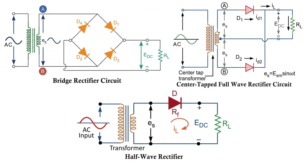
Half-Wave Rectifier
The Half-Wave Rectifier uses a single diode to convert AC into pulsating DC. During the positive half-cycle of the AC input, the diode conducts and allows current to flow through the load. During the negative half-cycle, the diode becomes reverse-biased and blocks current flow.
As a result, only one-half of the AC waveform appears across the load, making it the simplest but least efficient rectifier.
Main Characteristics:
- Uses only one diode.
- Simple and inexpensive circuit.
- High ripple content.
- Low rectification efficiency.
- Poor transformer utilization.
Center-Tapped Full-Wave Rectifier
A Center-Tapped Full-Wave Rectifier uses a center-tapped transformer and two diodes. One diode conducts during the positive half-cycle, while the other conducts during the negative half-cycle.
Because both halves of the AC waveform contribute to the output, the resulting DC voltage is smoother and more efficient than a half-wave rectifier.
Main Characteristics:
- Uses two diodes.
- Requires a center-tapped transformer.
- Higher efficiency.
- Lower ripple factor.
- Higher PIV requirement for diodes.
Bridge Rectifier
A Bridge Rectifier uses four diodes arranged in a bridge configuration. It does not require a center-tapped transformer.
During each half-cycle, two diodes conduct simultaneously, ensuring that current through the load always flows in the same direction.
Because of its high efficiency, low ripple, low PIV requirement, and better transformer utilization, the bridge rectifier is the most widely used rectifier in practical power supplies.
Main Characteristics:
- Uses four diodes.
- No center-tapped transformer required.
- High rectification efficiency.
- Lower PIV requirement.
- Excellent transformer utilization.
Mathematical Parameters of Rectifier
Before comparing the rectifiers, it is useful to understand the symbols used in the equations.
- Im = Maximum or peak load current
- Esm = Peak secondary voltage of transformer
- RL = Load resistance
- Rf = Forward resistance of diode
- Rs = Secondary winding resistance of transformer
- IDC = Average DC output current
- EDC = Average DC output voltage
- IRMS = RMS load current
- PDC = DC power delivered to load
- PAC = AC power supplied from transformer
- η = Rectifier efficiency
- γ = Ripple factor
- TUF = Transformer Utilization Factor
- PIV = Peak Inverse Voltage
Half-Wave vs Center-Tapped Full-Wave vs Bridge Rectifier

Parameter Analysis
Number of Diodes
The Half-Wave Rectifier requires only one diode, making the circuit extremely simple and economical. The Center-Tapped Full-Wave Rectifier requires two diodes, whereas the Bridge Rectifier requires four diodes arranged in a bridge network. Although the bridge rectifier uses more diodes, its overall performance is superior.
Average DC Output Current
The average DC current represents the useful DC component delivered to the load.
Half-Wave: IDC = Im/π
Full-Wave: IDC = 2Im/π
Bridge: IDC = 2Im/π
The full-wave and bridge rectifiers produce nearly twice the average DC current of a half-wave rectifier.
Maximum Load Current (Im)
The maximum load current is the peak value of current flowing through the load. For practical (non-ideal) rectifiers, it depends on the peak secondary voltage and the total resistance in the conducting path.
Half-Wave: Im = Esm / (Rs + Rf + RL)
Full-Wave: Im = Esm / (Rs + Rf + RL)
Bridge: Im = Esm / (Rs + 2Rf + RL)
The bridge rectifier has a slightly lower peak current because two diodes conduct simultaneously, introducing twice the diode forward resistance into the current path.
RMS Output Current (IRMS)
The RMS current represents the effective value of the load current that produces the same heating effect as an equivalent DC current.
Half-Wave: IRMS = Im/2
Full-Wave: IRMS = Im/√2
Bridge: IRMS = Im/√2
The full-wave and bridge rectifiers provide a higher RMS current than the half-wave rectifier because current flows through the load during both half-cycles of the AC input waveform.
Average DC Output Voltage
The average DC output voltage represents the useful DC component of the rectified output voltage. Full-wave and bridge rectifiers provide nearly twice the average DC voltage of a half-wave rectifier.
Half-Wave: EDC = Esm/π
Full-Wave: EDC = 2Esm/π
Bridge: EDC = 2Esm/π
The higher average DC output voltage of full-wave and bridge rectifiers enables more efficient power delivery to the load.
AC Power Input (PAC)
The AC power input is the total power supplied from the AC source to the rectifier circuit.
Half-Wave: PAC = IRMS2RL = Im2(Rs + Rf + RL)/4
Full-Wave: PAC = IRMS2RL = Im2(Rs + Rf + RL)/2
Bridge: PAC = IRMS2RL = Im2(Rs + 2Rf + RL)/2
The full-wave and bridge rectifiers draw more AC power from the source but convert it more efficiently into useful DC output.
DC Power Output (PDC)
The DC power output is the useful power delivered to the load by the DC component of the rectified current.
Half-Wave: PDC = IDC2RL = Im2RL/π2
Full-Wave: PDC = IDC2RL = 4Im2RL/π2
Bridge: PDC = IDC2RL = 4Im2RL/π2
The full-wave and bridge rectifiers deliver approximately four times the DC power output of a half-wave rectifier for the same peak current.
Rectification Efficiency
Rectification efficiency is defined as the ratio of DC power output to AC power input.
η = PDC / PAC
The theoretical maximum efficiencies are:
- Half-Wave Rectifier = 40.6%
- Center-Tapped Full-Wave Rectifier = 81.2%
- Bridge Rectifier = 81.2%
Full-wave and bridge rectifiers convert AC power into DC power much more efficiently.
Ripple Factor
Ripple factor indicates the amount of AC component present in the rectified output.
γ = IAC / IDC
Lower ripple factor means smoother DC output.
- Half-Wave Rectifier = 1.21
- Center-Tapped Full-Wave Rectifier = 0.482
- Bridge Rectifier = 0.482
Therefore, full-wave and bridge rectifiers provide significantly smoother DC output.
Peak Inverse Voltage (PIV)
PIV is the maximum reverse voltage a diode must withstand without breakdown.
PIV = Maximum Reverse Voltage Across Diode
- Half-Wave Rectifier = Esm
- Center-Tapped Full-Wave Rectifier = 2Esm
- Bridge Rectifier = Esm
The bridge rectifier has a significant advantage because each diode requires only half the PIV rating compared to the center-tapped full-wave rectifier.
Ripple Frequency
Ripple frequency determines how frequently ripple components appear in the output waveform.
- Half-Wave Rectifier = Supply Frequency (f)
- Center-Tapped Full-Wave Rectifier = 2f
- Bridge Rectifier = 2f
For a 50 Hz supply:
- Half-Wave Rectifier = 50 Hz Ripple
- Full-Wave Rectifier = 100 Hz Ripple
- Bridge Rectifier = 100 Hz Ripple
Higher ripple frequency makes filtering easier.
Transformer Utilization Factor (TUF)
Transformer Utilization Factor indicates how effectively the transformer rating is utilized.
TUF = DC Power Delivered to Load / AC Rating of Transformer
- Half-Wave Rectifier = 0.287
- Center-Tapped Full-Wave Rectifier = 0.693
- Bridge Rectifier = 0.812
The bridge rectifier provides the highest transformer utilization, making it the most economical choice in power supply design.
Advantages and Disadvantages
| Rectifier Type | Advantages | Disadvantages |
|---|---|---|
| Half-Wave | Simple, low cost, uses one diode | Low efficiency, high ripple, poor TUF |
| Center-Tapped Full-Wave | Higher efficiency, lower ripple | Requires center-tapped transformer and higher PIV diodes |
| Bridge | High efficiency, low ripple, better TUF, low PIV requirement | Uses four diodes and has two diode drops in conduction path |
Which Rectifier is Best?
For modern power supply applications, the Bridge Rectifier is generally considered the best choice because it offers:
- High rectification efficiency (81.2%).
- Low ripple content.
- No center-tapped transformer requirement.
- Lower diode PIV rating.
- Highest transformer utilization factor.
- Reduced transformer size and cost.
Because of these advantages, bridge rectifiers are widely used in adapters, battery chargers, SMPS input stages, industrial power supplies, and consumer electronics.
Conclusion
Half-Wave, Center-Tapped Full-Wave, and Bridge Rectifiers all perform AC-to-DC conversion, but their performance differs considerably. The Half-Wave Rectifier is simple but inefficient, while the Center-Tapped Full-Wave Rectifier offers improved efficiency and reduced ripple. Among all three, the Bridge Rectifier provides the best overall performance due to its high efficiency, lower PIV requirement, excellent transformer utilization factor, and smoother DC output. For this reason, bridge rectifiers are the preferred choice in most modern electronic power supply designs.
Centre-Tap Full-Wave Rectifier Circuit Design and Performance Analysis
Rectifier Circuit: Construction, Working, Types and Applications
Types of Diodes: Symbol, Working, Characteristics and Applications
Diode Clipper Circuit Diagram, Types, Working and Applications
Diode Clamper Circuit Diagram, Types, Working and Applications
