A rectifier is an electronic circuit or device that converts Alternating current (AC) into Direct current (DC) by allowing current to flow in only one direction, typically using semiconductor components such as diodes or controlled devices like thyristors. It enables AC-powered sources to operate devices that require a stable unidirectional DC voltage. This conversion is essential because most electronic components ranging from low-power signal circuits to high-power industrial systems are designed to function with DC supply.
At its core, rectification relies on the directional conduction property of semiconductor devices, primarily diodes, which allow current to pass in one direction while blocking it in the opposite direction. By strategically arranging these components, rectifier circuits transform sinusoidal AC waveforms into unidirectional pulsating DC, which can be further smoothed using filtering techniques.
Rectifiers are widely integrated into power supplies, battery charging systems, communication equipment, and control circuits. Their design varies depending on the required output quality, efficiency, and application constraints, leading to different configurations such as half-wave, full-wave, and bridge rectifiers.
Rectifier Circuit Symbol
In electrical and electronic representations, a rectifier circuit is depicted using two complementary approaches depending on the level of detail required: functional (block) symbols and circuit-level symbols.
Functional (Block) Symbol
The block symbol represents the rectifier as a conversion unit rather than showing its internal components. It is typically drawn as a square or rectangle divided diagonally:

- The AC side is indicated by a sine wave (~)
- The DC side is shown using a straight line with a dashed/solid combination (⎓)
- Input and output terminals are marked on opposite sides
This form is widely used in system diagrams and power supply layouts, where the emphasis is on the transformation of electrical energy from AC to DC rather than on implementation details.
Circuit-Level Symbol (Diode Representation)
At the schematic level, a rectifier is illustrated using diode symbols, since diodes are the fundamental elements enabling rectification. Each diode is represented by:
- A triangle (anode) indicating the direction of conventional current
- A vertical line (cathode) indicating the blocking direction
Different rectifier configurations are identified by how these diodes are arranged:
- Half-wave rectifier → single diode
- Full-wave (center-tapped) → two diodes with transformer
- Bridge rectifier → four diodes in a bridge arrangement
The block symbol conveys the function (AC to DC conversion), while the diode-based symbol explains the implementation. In professional documentation, both are used together starting with the block representation for conceptual clarity, followed by circuit symbols for technical depth.
Related Articles
- 5V Power Supply Circuit with LM7805 Voltage Regulator IC
- Dual Power Supply Circuit ±(5V, 12V, 15V, 24V & 1.25V-30V DC)
- Types of Diodes with Symbol, Definition, Working and Applications
- Diode Clipper Circuit Diagram, Types, Working and Applications
- Diode Clamper Circuit Diagram, Types, Working and Applications
- Power Diode: Symbol, Construction, Working, Types & Applications
- LED – Symbol, Construction, Working, Types and Applications
- Laser Diode – Symbol, Construction, Working, Types & Applications
Working of Rectifier Circuit
The operation of a rectifier circuit is based on the unidirectional conduction property of diodes, which allows current to flow in only one direction. By exploiting this behavior, the circuit converts an alternating input into a pulsating direct output.
Principle of Operation
An alternating current (AC) signal continuously changes polarity, producing positive and negative half cycles. A rectifier selectively permits current during specific intervals of this waveform:
- During forward bias, the diode conducts and allows current to pass
- During reverse bias, the diode blocks current flow
This selective conduction reshapes the AC waveform into a unidirectional (DC) form.
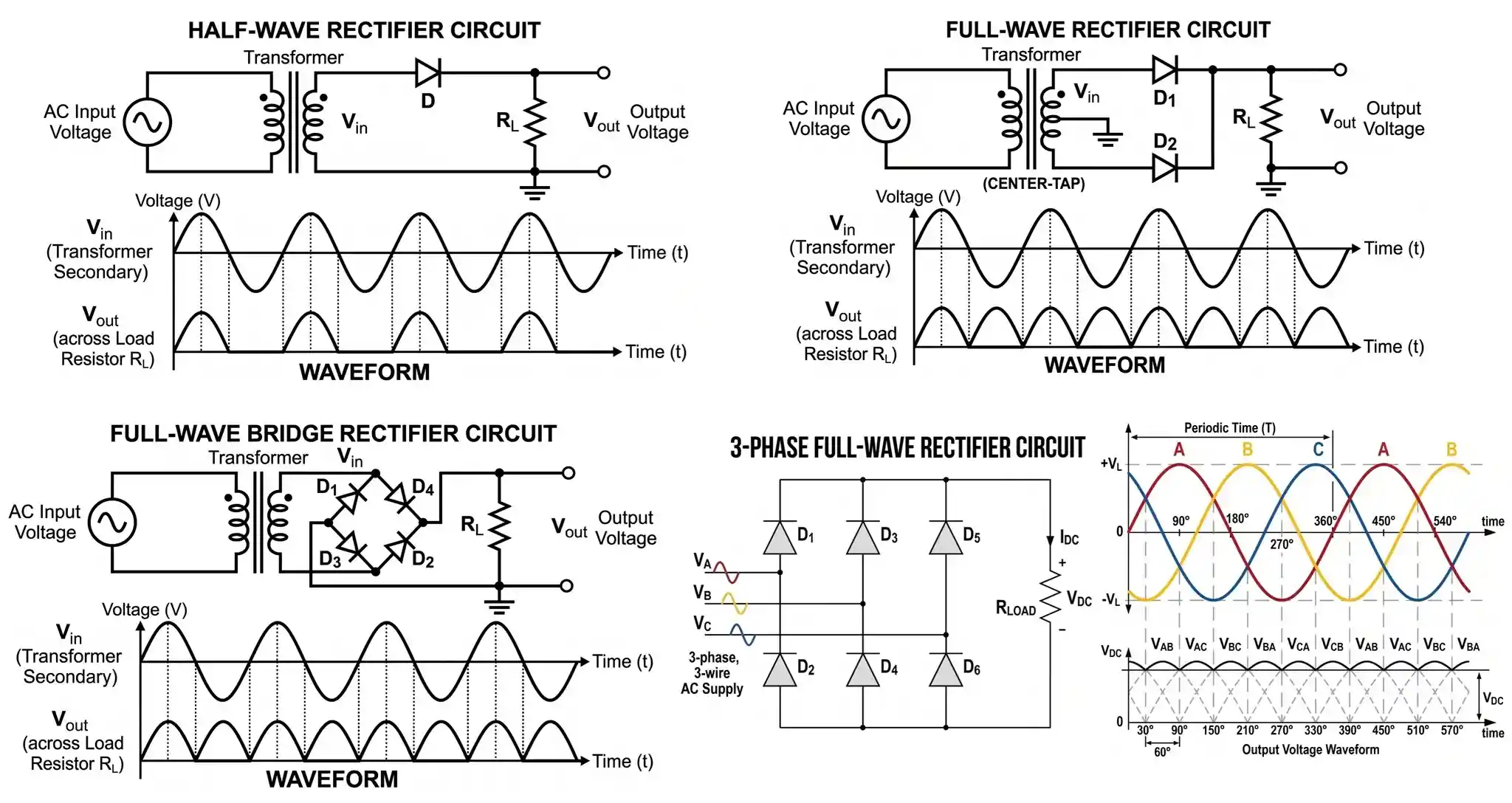
Half-Wave Rectification
In a half-wave rectifier, a single diode is connected in series with the load:
- Positive half cycle: The diode becomes forward biased and conducts, allowing current through the load
- Negative half cycle: The diode is reverse biased and blocks current
As a result, only one half of the AC waveform appears at the output, producing a pulsating DC with large gaps.
Full-Wave Rectification
Full-wave rectification utilizes both halves of the AC input, significantly improving output quality.
- Center-Tapped Full-Wave
- Two diodes are connected to a center-tapped transformer
- Each diode conducts during alternate half cycles
- Current through the load flows in the same direction for both halves
- Bridge Rectifier
- Four diodes are arranged in a bridge configuration
- During each half cycle, a pair of diodes conducts while the other pair blocks
- The load current direction remains constant, regardless of input polarity
This results in a continuous pulsating DC waveform, with higher average output and reduced ripple compared to half-wave rectification.
Output Characteristics
Although the output is unidirectional, it is not perfectly smooth. It consists of pulsations (ripples) corresponding to the input frequency:
- Half-wave → ripple frequency equals input frequency
- Full-wave → ripple frequency is doubled
To obtain a steady DC supply, the rectified output is typically passed through filter circuits (such as capacitors or inductors). The essence of rectifier operation lies in controlling current flow using diode biasing, ensuring that the load always receives current in one direction, thereby achieving AC to DC conversion efficiently.
Types of Rectifier Circuits
Rectifier circuits are broadly classified based on circuit configuration and control over the output voltage. This leads to two primary categories:
- Uncontrolled Rectifiers (Diode-based)
- Controlled Rectifiers (Thyristor-based)
Each type differs in waveform quality, efficiency, and degree of control.
Uncontrolled Rectifiers (Diode-based)
Rectifier circuits are broadly classified based on how they utilize the AC input waveform and the arrangement of diodes. The three principal types are half-wave, full-wave (center-tapped), and bridge rectifiers. Each differs in efficiency, ripple characteristics, and circuit complexity.
Half-Wave Rectifier
This is the simplest rectifier configuration, consisting of a single diode connected in series with the load.

- Working Behavior
- Conducts only during the positive half cycle
- Blocks current during the negative half cycle
- Output consists of only one half of the waveform
- Output Characteristics
- Output waveform: Pulsating DC with large gaps
- Ripple frequency: Same as input frequency (f)
- Key Parameters
- Average DC output: Low
- Efficiency: ~40.6%
- Ripple factor: High (~1.21)
- Transformer Utilization Factor (TUF): Poor
Due to high ripple and low efficiency, it is rarely used in power supplies, but useful in signal detection and simple low-power applications.
Full-Wave Rectifier Circuit (Center-Tapped)
This configuration uses two diodes and a center-tapped transformer to utilize both halves of the AC input.

- Working Behavior
- Each diode conducts during alternate half cycles
- Both halves of the AC signal contribute to output
- Current through the load remains in same direction
- Output Characteristics
- Output waveform: Continuous pulsating DC
- Ripple frequency: 2f (double the input frequency)
- Key Parameters
- Efficiency: ~81.2%
- Ripple factor: Lower (~0.482)
- TUF: Better than half-wave
- Requires center-tapped transformer
Provides better performance but increases transformer complexity and cost.
Bridge Rectifier Circuit
A bridge rectifier uses four diodes arranged in a bridge configuration, eliminating the need for a center-tapped transformer.

- Working Behavior
- Two diodes conduct in each half cycle
- Alternate pairs switch conduction between cycles
- Ensures unidirectional current through the load
- Output Characteristics
- Output waveform: Smooth pulsating DC (same as full wave)
- Ripple frequency: 2f
- Key Parameters
- Efficiency: ~81.2%
- Ripple factor: ~0.482
- TUF: Higher than center-tapped
- Slight voltage drops due to two diode conduction paths
- Most widely used rectifier due to
- Better transformer utilization
- No center tap requirement
- Compact and cost-effective design
Comparative Overview
| Parameter | Half-Wave | Full-Wave (CT) | Bridge Rectifier |
|---|---|---|---|
| Number of Diodes | 1 | 2 | 4 |
| Efficiency | Low (~40.6%) | High (~81.2%) | High (~81.2%) |
| Ripple Factor | High | Moderate | Moderate |
| Ripple Frequency | f | 2f | 2f |
| Transformer Requirement | Simple | Center-tapped | Simple |
| Output Quality | Poor | Good | Very Good |
- Half-wave rectifier → Simple but inefficient
- Full-wave rectifier → Better performance and smoother output
- Bridge rectifier → Best balance of efficiency, cost, and practicality, making it the preferred choice in modern electronic systems
This classification forms the foundation for designing power supplies and understanding waveform shaping in electronic circuits.
Controlled Rectifiers (Phase-Controlled Rectifiers)
Controlled rectifiers employ thyristors (SCRs) instead of diodes, enabling regulation of the output voltage by varying the firing angle (α) – the instant at which the device is triggered within each AC cycle. Unlike diodes, an SCR remains non-conducting even under forward bias until a gate pulse is applied.
Principle of Operation
When an AC supply is applied:
- From 0 to α → SCR blocks current (even if forward biased)
- At α → Gate pulse triggers conduction
- From α to π → SCR conducts
- At π (natural commutation) → Current falls to zero and SCR turns OFF
By adjusting α (0° to 180°), the average DC output voltage is controlled.
Single-Phase Half-Wave Controlled Rectifier
- Configuration: One SCR in series with the load
- Working
- During positive half cycle, SCR is forward biased
- It starts conducting only when triggered at angle α
- Conduction continues until the end of the half cycle (π)
- No conduction during negative half cycle
- Output Characteristics
- Output waveform: Delayed pulsating DC
- Average output voltage depends strongly on α
- Ripple: High
- Conduction angle: (π − α)
- Features
- Simplest controlled rectifier
- Poor output quality
- Used in low-power control applications
Single-Phase Full-Wave Controlled Rectifier
Midpoint (Center-Tapped) Controlled Rectifier
- Configuration: Two SCRs with center-tapped transformer
- Working
- Each SCR conducts in alternate half cycles
- Triggering is controlled independently for each half
- Current through load remains unidirectional
- Output Characteristics
- Output waveform: Full-wave controlled DC
- Ripple frequency: 2f
- Better average output than half-wave
- Requires precise synchronization of gate pulses
Fully Controlled Bridge Rectifier (Full Converter)
- Configuration: Four SCRs in bridge arrangement
- Working
- Two SCRs conduct per half cycle
- By controlling firing angles, output voltage can be varied continuously
- Can operate in rectification and inversion modes (for certain loads)
- Output Characteristics
- Output waveform: Fully controlled DC
- Wide range of output voltage (including negative for specific conditions)
- Ripple frequency: 2f
- High efficiency and flexibility
- Features
- Most versatile controlled rectifier
- Widely used in industrial drives
Single-Phase Semi-Controlled Bridge Rectifier (Half-Controlled)
- Configuration: Two SCRs + two diodes
- Working
- SCRs control conduction in one half cycle
- Diodes conduct automatically in the other half
- Output cannot be fully reversed
- Output Characteristics
- Output waveform: Partially controlled DC
- Average voltage depends on α
- Lower ripple compared to half-wave
- Features
- Simpler than fully controlled bridge
- Limited control range
- Cost-effective solution
Key Performance Parameters
- Firing Angle (α): Controls output voltage
- Conduction Angle: Duration of SCR conduction
- Average Output Voltage: Decreases as α increases
- Ripple Factor: Improves with multi-phase systems
- Power Factor: Decreases as α increases
Controlled rectifiers transform rectification from a passive conversion process into an actively regulated system. By adjusting the firing angle, they enable precise control over voltage and power, making them indispensable in applications such as DC motor drives, industrial heating, HVDC transmission, and controlled power supplies.
Advance Three Phase Rectifier Configurations
Advance rectifier topologies are designed to meet high-power, low-ripple, and high-efficiency requirements that cannot be satisfied by basic single-phase circuits. These configurations are widely used in industrial drives, power transmission, and large-scale power supplies.
Three-Phase Uncontrolled Rectifiers
Three-phase rectifiers utilize a three-phase AC supply, which inherently provides smoother output due to overlapping phase voltages.
3-Phase Half-Wave Rectifier Circuit
- Configuration: Three diodes, one per phase
- Working:
- Each diode conducts when its phase voltage is maximum
- Conduction shifts sequentially across phases
- Characteristics:
- Output waveform: Pulsating DC with reduced ripple
- Ripple frequency: 3f
- Simple but less efficient than bridge configurations
3-Phase Full-Wave Rectifier Circuit (Six-Pulse)

- Configuration: Six diodes
- Working:
- Two devices conduct at a time (one from positive group, one from negative group)
- Each device conducts for 120°
- Produces six pulses per cycle
- Characteristics:
- Output waveform: Much smoother DC
- Ripple frequency: 6f
- High efficiency and better transformer utilization
- Applications:
- Industrial DC drives
- Battery charging systems
- HVDC converter stations
Three-Phase Twelve-Pulse Rectifier Circuit

- Configuration: Two six-pulse rectifiers connected with phase-shifted transformers using star-delta configurations on secondary side of transformer.
- Working:
- Phase shift (typically 30°) cancels certain harmonics
- Outputs are combined to produce smoother DC
- Characteristics:
- Ripple frequency: 12f
- Very low harmonic distortion
- Improved power quality
- Applications:
- High-power industrial systems
- HVDC transmission
- Large motor drives
Three-Phase Controlled Rectifiers
By replacing diodes with SCRs, three-phase rectifiers gain controllability. Used in high-power applications where smoother DC is required.
3-Phase Half-Wave Controlled Rectifier

- Configuration: Three SCRs (one per phase)
- Output waveform has less ripple than single-phase
- Limited efficiency
3-Phase Full Wave Converter (Six-Pulse Rectifier)
- Configuration: Six SCRs
- Working
- Each SCR conducts for 120°
- Continuous conduction with overlapping phases

- Output Characteristics
- Output waveform: Nearly smooth DC
- Ripple frequency: 6f
- High efficiency and power handling
Three-Phase Semi-Controlled Rectifier
- Configuration: 3 SCRs + 3 diodes
- Partial control
- Lower cost than full converter
- Improved performance over single-phase
Multi-Pulse Rectifiers (18-Pulse, 24-Pulse)
These are extensions of the twelve-pulse concept using multiple phase-shifted supplies using star and delta configurations.
- Key Features:
- Extremely low ripple
- Significant harmonic reduction
- High system complexity and cost
- Use Cases:
- Aerospace systems
- Sensitive industrial equipment
- High-performance power electronics
Special Rectifier Configurations
Active (PWM) Rectifiers
- Use power electronic switches (IGBTs/MOSFETs)
- Employ pulse-width modulation (PWM)
- Provide bidirectional power flow and near-unity power factor
- Applications:
- Renewable energy systems
- Electric vehicles
- Modern power supplies
Voltage Doubler and Multiplier Rectifiers
- Configuration: Diodes and capacitors arranged in stages
- Working:
- Successive charging and stacking of voltages
- Produces output greater than peak input voltage
- Characteristics:
- High voltage, low current output
- Increased ripple with more stages
- Applications:
- CRTs, X-ray systems
- High-voltage testing equipment
Synchronous Rectifiers
- Replace diodes with controlled switches
- Reduce conduction losses
- Improve efficiency in low-voltage applications
- Applications:
Comparative Insight
| Configuration | Ripple | Complexity | Efficiency | Typical Use |
|---|---|---|---|---|
| 3-Phase Half-Wave | Moderate | Low | Medium | Basic industrial |
| 3-Phase Full-Wave (6-Pulse Bridge) | Low | Medium | High | Standard industrial drives |
| 12-Pulse | Very Low | High | Very High | HVDC, heavy industry |
| Multi-Pulse | Extremely Low | Very High | Excellent | Precision systems |
Advanced rectifier configurations represent a progression toward higher power quality, reduced harmonic distortion, and improved efficiency. By leveraging multi-phase inputs, phase shifting, and controlled switching, these systems deliver stable DC outputs suitable for demanding industrial and modern electronic applications.
Advantages of Rectifier Circuits
- Essential AC–DC Conversion
Rectifiers provide a reliable method of converting AC to DC, which is necessary for operating most electronic devices and control systems. - Simple and Cost-Effective Design
Basic rectifiers (especially diode-based) have minimal component requirements, making them economical and easy to implement. - High Reliability
With fewer moving parts and robust semiconductor devices, rectifier circuits offer long operational life and low failure rates. - Scalability Across Power Levels
Rectifiers can be designed for low-power electronics as well as high-power industrial applications, including multi-phase systems. - Improved Efficiency
Full-wave and bridge rectifiers achieve higher efficiency and better transformer utilization compared to simpler designs. - Compatibility with Filtering and Regulation
Rectified output can be easily improved using filters (capacitors/inductors) and voltage regulators to obtain smooth DC.
Disadvantages of Rectifier Circuits
- Ripple in Output
The output of a rectifier is not pure DC; it contains ripples that require additional filtering, increasing circuit complexity. - Harmonic Distortion
Rectifiers introduce harmonics into the supply, which can affect power quality and interfere with other equipment. - Power Losses
Semiconductor devices cause conduction and switching losses, often leading to heat generation and the need for heat sinks. - Poor Power Factor (Controlled Rectifiers)
Phase-controlled rectifiers can significantly degrade power factor, particularly at higher firing angles. - Transformer Requirement
Certain configurations (like center-tapped rectifiers) require special transformers, increasing size and cost. - Limited Output Quality Without Filtering
Without additional stages, the output is pulsating rather than steady, making it unsuitable for sensitive electronics directly.
Applications of Rectifier Circuits
Rectifier circuits are integral to systems that require conversion of input AC into usable DC power supply. Their applications span from low-power electronics to high-voltage industrial infrastructure.
- Power Supply Units (PSUs)
- Convert AC mains into DC for electronic circuits
- Used in adapters, chargers, and electronic devices
- Essential in both linear power supplies and SMPS
- Battery Charging Systems
- Convert AC input into controlled DC for charging
- Used in UPS systems, automotive chargers, and solar storage systems
- Controlled rectifiers regulate charging current and voltage
- DC Motor Drives and Speed Control
- Provide variable DC voltage for motor operation
- Enable speed regulation and torque control
- Widely used in industrial automation and electric traction systems
- Industrial Power Systems
- Supply stable DC for heavy-duty processes
- Used in:
- Electroplating and electrolysis
- DC welding equipment
- HVDC transmission systems
- Signal Detection and Demodulation
- Used in communication systems to extract signals
- Example: AM demodulation (envelope detection)
- Converts high-frequency AC into usable audio signals
- Renewable Energy Systems
- Convert generated AC into DC for storage or processing
- Used in wind energy systems
- Applied before battery storage or inverter stages
- Electronic Devices and Embedded Systems
- Present in almost all electronic equipment
- Used in:
- Computers, televisions, mobile devices
- Microcontrollers and embedded systems
- Measurement and Instrumentation
- Convert AC signals into measurable DC values
- Used in AC voltmeters and signal analyzers
- Enables accurate measurement of electrical parameters
Conclusion
Rectifier circuits serve as a critical interface between alternating current (AC) sources and direct current (DC) systems, enabling the operation of nearly all modern electronic and electrical equipment. From compact consumer devices to large-scale industrial installations, their presence is both fundamental and unavoidable.
They are extensively used across consumer electronics, industrial processes, and energy systems, demonstrating a wide operational scope. This versatility is reflected in their evolution from simple diode-based circuits to advanced controlled and multi-phase configurations, each tailored to specific performance and control requirements.
Despite their structural simplicity, rectifiers deliver a practical balance between efficiency, reliability, and cost-effectiveness. However, their performance is inherently influenced by factors such as circuit topology, control strategy, and load conditions. In many applications, achieving a stable and high-quality DC output necessitates the integration of filters, voltage regulators, or more sophisticated rectification techniques.
Here are some of the popular application specific rectifiers:
Low power AC rectification → 1N4007 / DB107
High current applications → 1N5408 / KBPC5010
High frequency (SMPS) → UF4007 / FR207
Efficiency critical (low loss) → 1N5819 (Schottky)
Compact PCB design → MB6S / SS34
In essence, rectifier circuits are indispensable to modern electrical and electronic infrastructure, forming the backbone of power conversion systems and enabling seamless interaction between AC supply networks and DC-driven technologies.
Types of Diodes with Symbol, Definition, Working and Applications
Diode Clipper Circuit Diagram, Types, Working and Applications
Diode Clamper Circuit Diagram, Types, Working and Applications
Light Emitting Diode LED – Symbol, Construction, Working, Types and Applications
Laser Diode – Symbol, Construction, Working, Types and Applications