A Linear Variable Differential Transformer (LVDT) is a precision electromechanical sensor used to measure linear displacement by converting mechanical motion into a proportional electrical signal. It belongs to the family of inductive transducers and operates without physical electrical contact between moving parts, which is a key reason for its durability and accuracy.
In modern engineering systems ranging from industrial automation to aerospace, accurate position feedback is essential. The LVDT fulfills this requirement by offering high sensitivity, excellent repeatability, and stable performance even under demanding environmental conditions.

Unlike resistive sensors, whose performance degrades due to wear and contact resistance, the LVDT relies on electromagnetic coupling, making it inherently robust and long-lasting. Its ability to detect extremely small displacements while maintaining linearity over a defined range makes it a preferred choice in precision measurement systems.
Definition of LVDT
A Linear Variable Differential Transformer (LVDT) is a non-contact inductive transducer that converts linear displacement into an electrical signal whose magnitude represents the amount of displacement and whose phase indicates the direction of movement.
This dual information, magnitude and direction, distinguishes LVDTs from many other displacement sensors and enables their use in closed-loop control systems.
Construction of LVDT
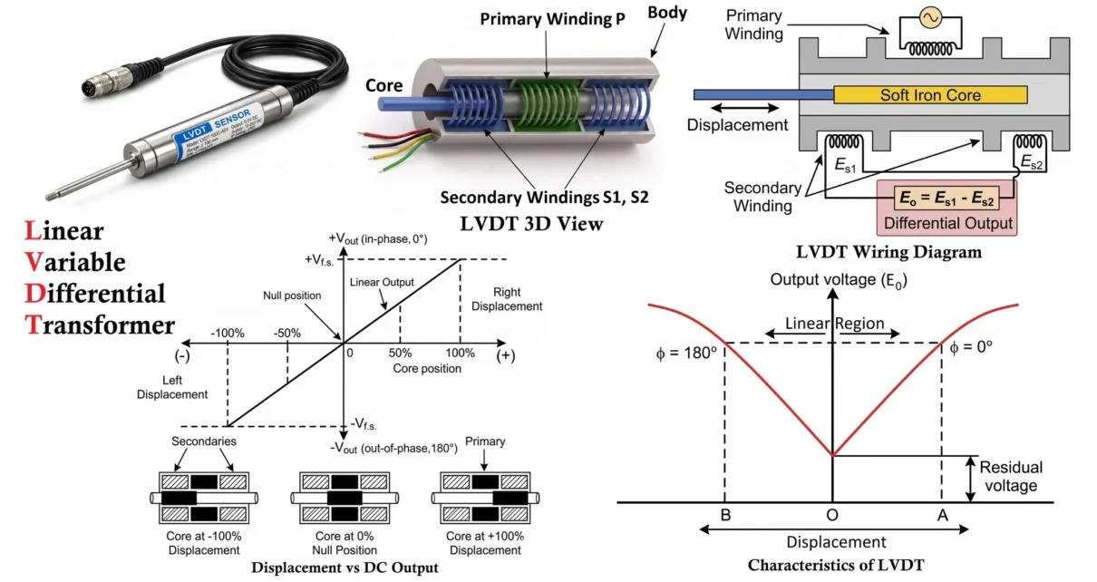
An LVDT is essentially a transformer-based device consisting of a stationary coil assembly and a movable magnetic core. Its construction is designed to ensure frictionless operation and precise displacement sensing.

The main components are:
- Primary Winding (P): The primary coil is placed at the center of the transformer and is excited by an AC supply. It generates an alternating magnetic field.
- Secondary Windings (S1 and S2): Two identical secondary coils are symmetrically placed on either side of the primary winding. These are connected in series opposition, meaning their outputs subtract from each other.
- Movable Ferromagnetic Core: A soft iron core is positioned inside the hollow former. It is mechanically connected to the object whose displacement is to be measured. The core can move freely without making electrical contact.
- Insulating Former and Housing: All windings are wound on a cylindrical insulating former and enclosed within a protective casing, which shields the device from environmental effects.
The symmetrical arrangement of secondary windings is critical, as it enables the device to detect both magnitude and direction of displacement.
Working Principle of LVDT
The operation of an LVDT is based on mutual induction and the differential voltage generated in the secondary windings due to core movement.

- Null Position (Core at Center)
- When the core is exactly at the center:
- Equal magnetic flux links both secondary windings (S1 and S2)
- Induced voltages in S1 and S2 are equal in magnitude but opposite in phase
- Hence, the differential output voltage is zero
- This position is called the null or zero position.
- Core Displacement in One Direction
- When the core moves toward one secondary coil (say S1):
- Magnetic coupling with S1 increases
- Induced voltage in S1 becomes greater than S2
- The differential output voltage becomes positive
- Core Displacement in Opposite Direction
- When the core moves toward the other secondary coil (S2):
- Magnetic coupling with S2 increases
- Induced voltage in S2 becomes greater than S1
- The output voltage becomes negative (phase reversal occurs)
- AC excitation → magnetic field generated
- Core movement → imbalance in secondary voltages
- Differential output → represents displacement
Characteristics of LVDT
The performance of an LVDT is best understood through its characteristic curves, which describe how the output behaves with respect to displacement. These characteristics are critical for evaluating accuracy, sensitivity, and usability in real applications.

- The magnitude of output voltage is proportional to displacement
- The phase of output indicates the direction of movement
- Within a certain range, the relationship between displacement and output is linear
Displacement vs DC Output Voltage
This is the most important characteristic of an LVDT.

- The graph is plotted between core displacement (X-axis) and output voltage (Y-axis)
- At the center (null position), the output voltage is zero
- As the core moves away from the center, the output voltage increases
- The output is linear over a specific range, known as the linear region
The straight-line portion of the graph represents accurate measurement. Beyond this region, nonlinearity starts to appear.
LVDT Specifications
The specifications of a Linear Variable Differential Transformer (LVDT) can vary depending on the specific model and the requirements of its intended application. However, some common specifications of LVDTs include:
Linearity
Linearity defines how closely the output follows a straight-line relationship with displacement.
- Ideal LVDT → perfectly linear response
- Practical LVDT → linear only within a limited range (typically ±5 mm to ±250 mm depending on design)
- Nonlinearity occurs at extreme core positions due to uneven magnetic coupling
Importance: High linearity ensures precise and predictable measurements in control systems.
Sensitivity
Sensitivity is the rate at which output voltage changes with displacement.
- It is given by the slope of the characteristic curve
- Unit: volts per millimeter (V/mm)
- Higher slope → higher sensitivity
Observation: Sensitivity is maximum near the null position and remains nearly constant within the linear range.
Phase Relationship (Direction Detection)
LVDT output is an AC signal, so phase plays a crucial role.
- At null position → no output (reference condition)
- Movement in one direction → output is in phase with primary voltage
- Movement in opposite direction → output is 180° out of phase
Key Role: Phase difference allows the LVDT to indicate not just magnitude but also direction of displacement.
Resolution
Resolution refers to the smallest displacement that can be detected.
- LVDT has virtually infinite resolution
- Limited only by signal conditioning electronics and noise
Advantage: This makes LVDT suitable for very fine measurements in precision systems.
Repeatability
Repeatability is the ability to produce the same output for repeated measurements of the same displacement.
- LVDTs exhibit excellent repeatability
- No mechanical contact → no wear and tear
Hysteresis
Hysteresis is the difference in output for the same displacement when approached from opposite directions.
- In LVDTs, hysteresis is very low
- Caused mainly by magnetic and mechanical imperfections
Temperature Stability
- Output may slightly vary with temperature due to resistance changes in coils
- High-quality LVDTs use temperature compensation techniques
Dynamic Response
- LVDT has a fast response time
- Suitable for both static and dynamic measurements
Overall Characteristic Behavior
- Zero output at null position
- Linear increase in output within working range
- Phase reversal for opposite direction
- Nonlinear behavior at extreme positions
Types of LVDT
LVDTs are classified based on their operating electronics and mechanical arrangement of the core. Each type is designed to suit specific measurement environments and application requirements.
Based on Output Signal / Electronics
AC LVDT
An AC LVDT provides an alternating current output signal and requires external signal conditioning.
- Requires an external oscillator and demodulator
- Output is typically in millivolts (AC signal)
- Needs additional circuits for amplitude detection and phase interpretation
Characteristics:
- High accuracy and flexibility
- Suitable for laboratory and industrial instrumentation systems
- More complex setup due to external electronics
DC LVDT
A DC LVDT has built-in signal conditioning circuitry, providing a direct DC output.
- Internal electronics perform rectification and filtering
- Output is a DC voltage proportional to displacement
- Easier to interface with control systems
Characteristics:
- Compact and user-friendly
- Reduced need for external circuitry
- Slightly higher cost due to integrated electronics
Based on Core Movement Mechanism
Free Core LVDT
In this type, the core is not mechanically attached to the coil assembly.
- Core moves freely inside the transformer
- Motion is transferred via external linkage
Characteristics:
- No mechanical friction between core and coil
- Suitable for applications requiring minimal mechanical loading
- Requires precise alignment
Spring-Loaded LVDT
This type includes a spring mechanism that keeps the core in contact with the measured object.
- Often used as a probe-type sensor
- Automatically returns to original position when force is removed
Characteristics:
- Ideal for thickness measurement and gauging
- Provides consistent contact force
- Common in quality control systems
Guided Core (Captive Core) LVDT
Here, the core is mechanically guided and attached to a rod.
- Core movement is constrained within a guided path
- Prevents misalignment and improves stability
Characteristics:
- Robust and reliable
- Suitable for industrial environments
- Slight mechanical friction may be present
Based on Application Range
Short Stroke LVDT
- Measures small displacements (microns to a few millimeters)
- High sensitivity and precision
Long Stroke LVDT
- Designed for larger displacements (up to several hundred millimeters)
- Used in heavy machinery and structural monitoring
LVDTs can be broadly categorized into:
- AC and DC types (based on output and electronics)
- Free core, spring-loaded, and guided core types (based on mechanical design)
- Short and long stroke types (based on measurement range)
Advantages of LVDT
LVDTs are widely preferred in precision measurement systems due to several strong technical advantages:
- High Accuracy and Linearity: LVDTs provide highly accurate measurements with excellent linearity over their operating range, making them suitable for precise control systems.
- Frictionless Operation: Since there is no physical electrical contact between the core and coils, mechanical wear is minimized, resulting in long service life.
- Infinite Resolution: Theoretically, LVDTs can detect infinitely small displacements. In practice, resolution is limited only by signal conditioning and noise levels.
- Excellent Repeatability: They can reproduce the same output for repeated measurements under identical conditions, which is essential in automation and testing systems.
- High Sensitivity: Even very small movements of the core produce measurable output changes, enabling fine displacement detection.
- Rugged and Durable: LVDTs can operate in harsh environments such as high vibration, temperature variations, and contaminated conditions.
- Electrical Isolation: There is complete isolation between input (excitation) and output, improving safety and reducing interference.
- Wide Measurement Range: Available in both short and long stroke designs, covering micrometer-level to large displacement measurements.
Disadvantages of LVDT
Despite their advantages, LVDTs also have certain limitations that must be considered:
- Requires Signal Conditioning: The output is an AC signal that needs demodulation and filtering, increasing system complexity (especially in AC LVDTs).
- Sensitive to External Magnetic Fields: Stray magnetic fields can affect accuracy, requiring magnetic shielding in some applications.
- Temperature Effects: Variations in temperature can influence coil resistance and output, necessitating compensation techniques.
- Larger Size Compared to Some Sensors: LVDTs are generally bulkier than alternatives like strain gauges or potentiometers.
- Alignment Requirement: Accurate operation depends on proper alignment of the core and coil assembly; misalignment can cause errors.
- Higher Cost: More expensive than simple displacement sensors due to precision construction and additional electronics.
Applications of LVDT
LVDTs are extensively used wherever precise linear displacement measurement is required. Their reliability, high sensitivity, and non-contact operation make them suitable for both industrial and scientific applications.
They are especially critical in systems where accurate position feedback directly affects performance and safety.
Industrial Automation and Control Systems
LVDTs are widely used in automated systems to monitor and control position.
- Position feedback in servo systems
- Monitoring movement of mechanical components
- Closed-loop control in manufacturing processes
Example: Used in automated assembly lines to ensure components move to exact positions.
Hydraulic and Pneumatic Systems
In fluid power systems, LVDTs are used for accurate position sensing of actuators.
- Measurement of piston displacement in hydraulic cylinders
- Valve position feedback in control systems
- Pressure control through displacement monitoring
Key Benefit: Provides real-time feedback for precise motion control.
Aerospace and Defense Systems
LVDTs are preferred in aerospace due to their robustness and reliability.
- Monitoring position of control surfaces (flaps, rudders)
- Landing gear position sensing
- Missile and defense system instrumentation
Reason for Use: They can operate reliably under extreme conditions such as vibration and temperature variations.
Machine Tools and CNC Systems
Precision machining requires accurate measurement of tool and workpiece position.
- Tool position feedback in CNC machines
- Alignment and calibration of machine components
- Monitoring cutting tool displacement
Material Testing Equipment
LVDTs are commonly used in laboratories and testing machines.
- Measurement of elongation, compression, and deformation
- Stress-strain analysis in materials
- Crack propagation studies
Example: Used in Universal Testing Machines (UTM) for precise displacement measurement.
Thickness and Dimension Measurement
Used in quality control processes for measuring dimensions.
- Thickness measurement in metal sheets and rolling mills
- Diameter and dimensional inspection
- Surface profiling
Vibration and Displacement Measurement
LVDTs can detect very small movements, making them useful for dynamic measurements.
- Monitoring vibrations in mechanical systems
- Structural displacement measurement
- Seismic and geotechnical applications
Power Plants and Energy Systems
In power generation systems, LVDTs are used for monitoring mechanical movement.
- Valve position in turbines
- Boiler expansion measurement
- Shaft displacement monitoring
Robotics and Precision Engineering
LVDTs are used in systems requiring high precision and repeatability.
- Position sensing in robotic arms
- Feedback in precision positioning systems
- Semiconductor manufacturing equipment
Conclusion
The Linear Variable Differential Transformer (LVDT) is widely regarded as a benchmark device for precision linear displacement measurement in modern instrumentation and control engineering. Its frictionless (non-contact) operation, high sensitivity, and excellent repeatability enable highly accurate and stable measurements over extended periods, even under demanding operating conditions.
One of the defining strengths of the LVDT is its ability to provide continuous, high-resolution output without mechanical wear, making it particularly suitable for critical and long-life applications. Additionally, its inherent features such as electrical isolation, robust construction, and immunity to mechanical fatigue further enhance its reliability in industrial and aerospace environments.
LVDTs offer exceptional precision, durability, and reliability, making them ideal for critical measurement systems. However, their cost, size, and need for signal conditioning must be considered during system design.
Although LVDTs require signal conditioning circuits and careful mechanical alignment, these considerations are relatively minor compared to the significant advantages they offer in terms of accuracy, durability, and consistency.
Consequently, LVDTs remain an essential component in a wide range of applications, from industrial automation and process control to aerospace systems and precision testing equipment where accurate position feedback is crucial for performance, safety, and system stability.
Frequently Asked Questions (FAQs)
Why is LVDT called a differential transformer?
Because its output voltage is derived from the difference between the voltages induced in two secondary windings, which varies with core displacement.
What type of signal does an LVDT produce?
An LVDT typically produces an AC output signal proportional to displacement. In DC LVDTs, this signal is internally conditioned to provide a DC output.
What is the null position in an LVDT?
The null position is the central position of the core where equal voltages are induced in both secondary coils, resulting in zero differential output voltage.
Can LVDT measure very small displacements?
Yes, LVDTs offer extremely high sensitivity and near-infinite resolution, allowing detection of very small displacements (limited mainly by noise and electronics).
What is the main advantage of LVDT over a potentiometer?
Unlike potentiometers, LVDTs are contactless devices, eliminating mechanical wear and significantly improving reliability and lifespan.
Why is signal conditioning required in LVDT?
Signal conditioning is needed to demodulate the AC output, extract amplitude and phase information, and convert it into a usable DC signal.
Is LVDT suitable for dynamic measurements?
Yes, LVDTs have a fast dynamic response, making them suitable for both static and rapidly changing displacement measurements.
Where is LVDT commonly used?
They are widely used in industrial automation, aerospace systems, hydraulic actuators, material testing equipment, and precision measurement applications.
What is a Sensor? Types of Sensors, Classification & Applications
Hall Effect Transducer Construction, Working and Applications
IOT Based Air Quality Monitoring System with ESP32 & BME680 Sensor
Explore Essential Drone Sensors for Precise Flight Navigation
