In this article, we will study the circuit design, working principle, mathematical analysis, performance parameters, advantages, disadvantages, and practical applications of the Half-Wave Rectifier in detail.
Electronic circuits such as computers, televisions, communication equipment, battery chargers, and industrial control systems require a direct current (DC) supply for proper operation. However, the electrical power available from utility lines is in the form of alternating current (AC). Therefore, a conversion process is required to transform AC power into DC power.
Related Articles
- Rectifier Circuit: Construction, Working, Types and Applications
- 5V Power Supply Circuit with LM7805 Voltage Regulator IC
- Dual Power Supply Circuit ±(5V, 12V, 15V, 24V & 1.25V-30V DC)
- Types of Diodes with Symbol, Definition, Working and Applications
- Diode Clipper Circuit Diagram, Types, Working and Applications
- Diode Clamper Circuit Diagram, Types, Working and Applications
- Power Diode: Symbol, Construction, Working, Types & Applications
- LED – Symbol, Construction, Working, Types and Applications
- Laser Diode – Symbol, Construction, Working, Types & Applications
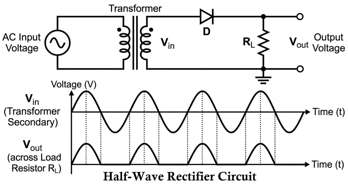
Half-Wave Rectifier Circuit
A Half-Wave Rectifier is an electronic circuit that converts alternating current (AC) into pulsating direct current (DC) by allowing only one half-cycle of the input AC waveform to pass through the load while blocking the other half-cycle.
The rectification process is achieved using a single PN junction diode. During one half-cycle of the AC input, the diode becomes forward biased and conducts current. During the opposite half-cycle, the diode becomes reverse biased and blocks current flow.
Because only half of the input waveform contributes to the output, the circuit is called a Half-Wave Rectifier.
Characteristics of Half-Wave Rectifier:
- Uses only one diode as the rectifying element.
- Converts AC into pulsating DC.
- Conducts during only one half-cycle of the input waveform.
- Produces a discontinuous output current.
- Has a high ripple content.
- Has a maximum theoretical efficiency of 40.6%.
- Requires fewer components and is easy to design.
- Suitable for low-power applications.
Most electronic circuits require a stable DC voltage source for proper operation, such as microcontroller circuits, digital electronics, communication systems, battery charging circuits, LED power supplies, and instrumentation systems.
The Half-Wave Rectifier represents the most basic method of accomplishing this conversion and serves as the foundation for understanding more advanced rectifier circuits such as:
- Full-Wave Rectifier
- Center-Tapped Full-Wave Rectifier
- Bridge Rectifier
- Controlled Rectifier Circuits
Principle of Half-Wave Rectification
The operation of a Half-Wave Rectifier is based on the unidirectional conduction property of a PN junction diode. A diode allows current to flow when it is forward biased and blocks current when it is reverse biased. This property enables the rectifier to pass only one half of an alternating current (AC) waveform while suppressing the other half, thereby producing a pulsating direct current (DC) output.
Forward Bias Condition
When the anode of the diode becomes positive with respect to the cathode:
- The depletion region narrows.
- The barrier potential decreases.
- Current flows through the diode.
- Silicon diode forward voltage drop: VF ≈ 0.7 V
- Germanium diode forward voltage drop: VF ≈ 0.3 V
The diode current under forward bias is given by:
ID = IS [e(VD/ηVT) − 1]
ID = Diode current
IS = Reverse saturation current
VD = Voltage across the diode
η = Ideality factor
VT = Thermal voltage (approximately 26 mV at room temperature)
Reverse Bias Condition
When the anode becomes negative with respect to the cathode:
- The depletion region widens.
- The barrier potential increases.
- Current flow becomes nearly zero.
Under reverse bias: ID ≈ −IS
Thus, the diode behaves almost like an open switch and prevents current from flowing through the circuit.
Construction of Half-Wave Rectifier Circuit
The Half-Wave Rectifier is one of the simplest rectifier circuits used for converting alternating current into direct current. The circuit requires only a few components and can be easily assembled for educational, laboratory, and low-power electronic applications.

A practical Half-Wave Rectifier consists of a step-down transformer, a PN junction diode, a load resistor (RL), and connecting wires arranged in a simple series configuration.
Step-Down Transformer
The transformer performs two important functions:
- Provides electrical isolation from the AC mains supply.
- Converts the mains voltage to the desired AC voltage level.
For example, a 230 V AC mains supply may be stepped down to 12 V AC or 24 V AC depending on the application.
The voltage transformation ratio is given by:
N 2 / N1 = ESM / EPM = ES / EP
- N 1 = Primary turns
- N 2 = Secondary turns
- EP = Primary RMS voltage
- ES = Secondary RMS voltage
- EPM = Primary Maximum voltage
- ESM = Secondary Maximum voltage
This relationship determines the voltage available at the rectifier input.
PN Junction Diode
The diode acts as the rectifying element of the circuit.
- Conduct current during the positive half-cycle.
- Block current during the negative half-cycle.
- Convert the alternating waveform into a unidirectional waveform.
During conduction, the load current is approximately:
iL = Vm sin(ωt) / (rf + RL)
Vm = Peak secondary voltage
rf = Forward resistance of the diode
RL = Load resistance
Load Resistance (RL)
The load resistor represents the external device or circuit that consumes the rectified power.
The output voltage is developed across this resistor. According to Ohm’s law:
VL = IL × RL
VL = Load voltage
IL = Load current
RL = Load resistance
Working of Half-Wave Rectifier Circuit
When AC voltage is applied, the diode conducts during the positive half-cycle and blocks during the negative half-cycle. As a result, only one half of the input waveform appears across the load, producing a pulsating DC output.
The operation of a Half-Wave Rectifier can be understood by analyzing the behavior of the circuit during both halves of the AC input cycle. The transformer secondary provides a sinusoidal voltage that continuously alternates between positive and negative values.

The AC voltage supplied by the transformer secondary winding is sinusoidal and can be expressed as:
es = ESM sin(ωt)
es = Instantaneous secondary voltage
ESM = Peak secondary voltage
ω = Angular frequency
t = Time
The angular frequency is given by ω = 2πf, f is the supply frequency. The RMS and peak values of the secondary voltage are related by:
ESM = √2 × ES or ES = ESM / √2
Since the input voltage alternates continuously, the operation of the rectifier can be divided into positive and negative half-cycle operation.
Positive Half-Cycle Operation
During the positive half cycle 0 ≤ ωt ≤ π, the upper end of the transformer secondary becomes positive with respect to the lower end.
- The anode of the diode becomes positive.
- The cathode becomes negative.
- The diode becomes forward biased.
- Current flows through the circuit.
Current Path: Transformer Secondary → Diode → Load Resistance (RL) → Transformer Secondary
Load Current and Voltage During Positive Half Cycle:
iL = es / (rf + RL)
iL = ESM sin(ωt) / (rf + RL)
ESM = Im (rf + RL)
iL = Im sin(ωt)
This shows that the load current follows the positive half (0 ≤ ωt ≤ π) of the sinusoidal waveform.
The voltage across the load resistor is:
vL = iLRL = ImRLsin(ωt)
Thus, the output voltage follows the positive half of the input sinusoidal waveform. During the positive half-cycle, the diode is forward biased and acts as a closed switch, allowing current to flow through the load. The load receives power, and the output voltage is positive.
Negative Half-Cycle Operation
During the interval π ≤ ωt ≤ 2π the transformer secondary polarity reverses, causing the diode to become reverse biased. The diode behaves as an open switch and blocks current flow.
Load Current and Voltage During Negative Half Cycle:
iL = 0
vL = 0
During the negative half-cycle, the diode is reverse biased and acts as an open switch, preventing current flow through the load. No current flows through the load and no output voltage appears across it.
Input and Output Waveforms
The input to the rectifier is a complete sinusoidal AC waveform containing both positive and negative half cycles. However, the output waveform is different because the diode blocks one half of the input signal.

Input Waveform:
The transformer secondary voltage is:
es = ESM sin(ωt)
- Waveform is pure sinusoidal
- Contains positive and negative half cycles
- Frequency equal to the supply frequency
Output Waveform:
The output voltage consists only of positive half cycles because the diode blocks the negative half cycles.
- Negative half cycles are removed
- Output becomes unidirectional
- Output is discontinuous
- Average value is positive
- Contains large ripple content
The resulting waveform is known as a pulsating DC waveform, voltage maintains the same polarity but its magnitude varies continuously.
A battery produces nearly constant DC voltage, whereas a Half-Wave Rectifier produces a varying DC voltage. Therefore, filter circuits are often connected after the rectifier to reduce fluctuations and obtain a smoother DC output.
Frequency of Rectifier Output:
The output pulse appears once during every cycle of the AC input signal. Therefore, the output frequency is equal to the input frequency.
fout = fin
- For a 50 Hz AC supply: fout = 50 Hz
- For a 60 Hz AC supply: fout = 60 Hz
This low ripple frequency is one of the major disadvantages of a Half-Wave Rectifier because filtering becomes more difficult when compared with Full-Wave Rectifier circuits.
Performance Analysis of Half-Wave Rectifier
The output of a Half-Wave Rectifier is not a pure DC quantity. Instead, it consists of positive half-sinusoidal pulses separated by intervals of zero output. Therefore, various performance parameters are used to evaluate the quality and effectiveness of rectification.
The most important parameters include:
- Average (DC) Load Current
- Average (DC) Output Voltage
- RMS Load Current
- RMS Output Voltage
- Form Factor
- Peak Factor
These quantities form the foundation for understanding the performance of any rectifier circuit.
Average (DC) Load Current (IDC)
The most useful component of the rectifier output is its average or DC value because it represents the actual DC current delivered to the load.
Since the output current exists only during the positive half cycle, the average value must be calculated over one complete cycle.
Mathematically:
The load current iL = im sin(ωt) for 0 ≤ ωt ≤ π and iL = 0 for π ≤ ωt ≤ 2π.
The average value of any periodic waveform is:
IDC = (1 / 2π) ∫ iL d(ωt)
Substituting the Half-Wave Rectifier current:
IDC = (1 / 2π) ∫₀π Im sin(ωt) d(ωt)
Taking Im outside the integral:
IDC = (Im / 2π) ∫₀π sin(ωt) d(ωt)
Integrating:
IDC = (Im / 2π) [-cos(ωt)]₀π
IDC = (Im / 2π) [1 + 1]
IDC = Im / π
Numerically, IDC = 0.318 Im
This means the DC component of the output current is only 31.8% of the peak current. The remaining portion contributes to AC ripple components.
Peak Load Current (Im): The maximum value of current occurs at the peak of the positive half cycle.
Applying Ohm’s law:
Im = ESM / (RL + rf + Rs)
ESM = Peak secondary voltage
RL = Load resistance
rf = Diode forward resistance
Rs = Transformer secondary resistance
If rf and Rs are neglected: Im ≈ ESM / RL
This simplified equation is commonly used in theoretical analysis.
Average (DC) Output Voltage (VDC)
The DC output voltage is the average voltage appearing across the load resistance.
Using Ohm’s law:
VDC = IDC RL
Substituting IDC:
VDC = (Im RL) / π
Substituting Im:
VDC = ESM RL / [π(RL + rf + Rs)]
This is the general expression for DC output voltage.
Practical Approximation:
In most practical circuits: RL >> (rf + Rs)
Therefore: VDC ≈ ESM / π or VDC ≈ 0.318 ESM
Only about 31.8% of the peak AC voltage is converted into useful DC voltage. This explains why the Half-Wave Rectifier has relatively poor performance compared to Full-Wave Rectifiers.
RMS Value of Load Current (IRMS)
The RMS (Root Mean Square) value represents the effective current that produces the same heating effect as an equivalent DC current.
Power calculations are based on RMS quantities, RMS value is obtained by squaring the waveform, finding the average value and taking the square root.
Mathematically:
IRMS = √[(1 / 2π) ∫ i2L d(ωt)]
Substituting:
IRMS = √[(1 / 2π) ∫₀π I2m sin2(ωt) d(ωt)]
Taking I2m outside:
IRMS = Im √[(1 / 2π) ∫₀π sin2(ωt) d(ωt)]
Using the identity:
sin2(ωt) = (1 − cos 2ωt)/2
Integrating,
IRMS = Im / 2
For a complete sine wave: IRMS = Im / √2
For a Half-Wave Rectified sine wave: IRMS = Im / 2
The RMS value is smaller because current flows only during half of the cycle.
RMS Value of Output Voltage (VRMS)
The RMS output voltage is obtained from the RMS current.
Using Ohm’s law:
VRMS = IRMS RL
Substituting:
VRMS = (Im RL) / 2
Substituting Im:
VRMS = ESM RL / [2(RL + rf + Rs)]
For an ideal rectifier:
VRMS ≈ ESM / 2
Relationship Between Peak, RMS, and Average Values of a Half-Wave Rectifier.
| Parameter | Expression | Numerical Value |
|---|---|---|
| Peak Current | Im | 1.0 Im |
| Average Current | Im / π | 0.318 Im |
| RMS Current | Im / 2 | 0.5 Im |
| Peak Voltage | ESM | 1.0 ESM |
| Average Voltage | ESM / π | 0.318 ESM |
| RMS Voltage | ESM / 2 | 0.5 ESM |
These relationships are frequently used in rectifier design calculations.
Form Factor
The Form Factor indicates how much the waveform differs from a pure DC waveform.
Form Factor = RMS Value / Average Value
For a Half-Wave Rectifier:
Form Factor = IRMS / IDC
Substituting:
Form Factor = (Im/2) / (Im/π)
Form Factor = π/2
Form Factor = 1.57
A pure DC waveform has 1 Form Factor, whereas half-wave rectifier has 1.57. This indicates that the output contains a significant amount of AC variation and is far from being pure DC.
Peak Factor (Crest Factor)
The Peak Factor indicates the ratio of peak value to RMS value.
Peak Factor = Peak Value / RMS Value
For current:
Peak Factor = Im / IRMS
Substituting:
Peak Factor = Im / (Im/2)
Therefore,
Peak Factor = 2
A higher Peak Factor indicates that the waveform contains sharp peaks relative to its effective value. This parameter is important when selecting diodes, transformers, and filter capacitors because these components must withstand peak current conditions.
DC Power Output (PDC)
The primary objective of a rectifier is to convert AC power into useful DC power. Since the load utilizes the average component of the rectified output, the DC power is calculated using the average (DC) current flowing through the load.
DC Power Output is the power delivered to the load resistance by the DC component of the rectifier output.
Mathematical Expression
The DC output power is given by:
PDC = IDC2RL
Substituting:
IDC = Im/π
we get,
PDC = (Im/π)2 RL
Therefore,
PDC = Im2RL/π2
Since 1/π2 = 0.1013
PDC = 0.1013 Im2RL
This power represents the useful power available to the load. A higher value of PDC indicates better utilization of the input AC power.
AC Power Input (PAC)
The AC power supplied by the transformer secondary is consumed by:
- Load resistance (RL)
- Diode forward resistance (rf)
- Transformer secondary resistance (Rs)
Therefore, the AC input power is determined using the RMS current.
Mathematical Expression:
The AC power supplied by the transformer is:
PAC = IRMS2 (RL + rf + Rs)
Substituting: IRMS = Im/2
PAC = (Im/2)2 (RL + rf + Rs)
PAC = Im2/4 × (RL + rf + Rs)
PAC = 0.25 Im2 (RL + rf + Rs)
PAC represents the total power drawn from the AC source. Part of this power is delivered to the load while the remaining portion is dissipated as heat in the diode and transformer winding resistance.
Rectification Efficiency (η)
One of the most important performance parameters of a rectifier is its efficiency. Efficiency indicates how effectively the rectifier converts AC power into useful DC power.
Rectification Efficiency is defined as the ratio of DC power delivered to the load to the AC power supplied to the rectifier.
Mathematically:
η = PDC / PAC
Substituting the expressions for PDC and PAC:
η = (Im2RL/π2) / [(Im2/4)(RL + rf + Rs)]
Cancelling Im2:
η = 4RL / [π2(RL + rf + Rs)]
Since 4/π2 = 0.406, the efficiency becomes
η = 0.406 RL / (RL + rf + Rs)
η = 0.406 / [1 + (rf + Rs)/RL]
Percentage Efficiency:
η(%) = 40.6 / [1 + (rf + Rs)/RL]
Maximum Rectification Efficiency:
For an ideal rectifier, rf = 0 Rs = 0
ηmax = 40.6%
This means that even under ideal conditions, only 40.6% of the AC input power is converted into useful DC power.
The remaining power appears as AC ripple components, heat losses and transformer losses. This low efficiency is one of the major disadvantages of the Half-Wave Rectifier.
Why Half-Wave Rectifier Efficiency is Low?
The efficiency of a Half-Wave Rectifier is low because:
- Current flows only during one half-cycle.
- The diode remains non-conducting during the other half-cycle.
- The transformer is utilized only half of the time.
- Large ripple components remain present in the output.
As a result, a considerable portion of the supplied AC power does not contribute to useful DC output. This is why Full-Wave and Bridge Rectifiers are preferred in practical power supplies.
Ripple Factor (γ)
Ripples are the residual AC components present in the rectified output. An ideal DC source should provide a constant voltage and current. However, the output of a Half-Wave Rectifier continuously rises and falls with time, these unwanted AC variations superimposed on the DC output.
They are responsible for:
- Output voltage fluctuations
- Reduced power quality
- Increased noise
- Poor performance of electronic circuits
The amount of ripple present in the output is measured using Ripple Factor. It measures how closely the output resembles pure DC.
Ripple Factor is defined as the ratio of the RMS value of the AC component present in the output to the DC component of the output.
γ = IAC / IDC
IAC = RMS value of AC component
IDC = Average DC component
The output current consists of DC component and AC component.
IRMS2 = IDC2 + IAC2
Rearranging,
IAC2 = IRMS2 − IDC2
Taking square root,
IAC = √(IRMS2 − IDC2)
Substituting into the ripple factor equation,
γ = √[(IRMS2 − IDC2) / IDC2]
γ = √[(IRMS / IDC)2 − 1]
This is the general ripple factor equation applicable to all rectifiers.
Ripple Factor of Half-Wave Rectifier:
Substituting IRMS = Im/2 and IDC = Im/π
γ = √[(π/2)2 − 1]
γ = √(2.467 − 1)
γ = √1.467 = 1.21
Ripple Factor = 1.21 means the AC ripple content is approximately 121% of the DC component. This is an extremely large value.
A large ripple factor indicates poor DC quality, large output fluctuations, requirement of filtering and low rectification performance. Therefore, the Half-Wave Rectifier is considered a poor AC-to-DC converter.
Ripple Factor and Output Quality: The ripple factor directly indicates the quality of the DC output.
- Smaller Ripple Factor: Better DC output, smaller voltage fluctuations, improved circuit performance, and easier filtering.
- Larger Ripple Factor: Poor DC output, higher noise levels, larger voltage fluctuations, and reduced efficiency.
For a pure DC source γ = 0. Since the Half-Wave Rectifier has γ = 1.21 its output is far from ideal.
Fourier Analysis of Half-Wave Rectifier Output
The pulsating output of a Half-Wave Rectifier can be represented as the sum of a DC component and several AC components. This analysis is based on Fourier Series.
Fourier Series Representation:
The load current can be expressed as:
iL = IDC + Fundamental Component + Harmonic Components
Components Present in Output: The complete waveform consists of a DC component, a fundamental frequency component, and harmonic components including the second harmonic, third harmonic, and higher-order harmonics.
DC Component: This is the useful output current.
IDC = Im/π
Fundamental Component: This component has the same frequency as the AC supply. For a 50 Hz input fundamental frequency is 50 Hz.
Harmonic Components: Additional frequency components appear at 2f, 3f, 4f, 5f, … These harmonic components contribute to ripple and waveform distortion.
Fourier analysis helps engineers:
- Design filter circuits
- Estimate ripple content
- Analyze harmonic distortion
- Improve power supply performance
It clearly shows that the output of a Half-Wave Rectifier is not pure DC but a combination of DC and multiple AC frequency components.
Peak Inverse Voltage (PIV)
Peak Inverse Voltage is defined as the maximum reverse voltage that a diode can withstand without entering the breakdown region.
One of the most important considerations in rectifier design is the maximum reverse voltage that the diode must withstand without breaking down.
If the reverse voltage across the diode exceeds its rated value, excessive reverse current may flow, leading to permanent damage of the diode. Therefore, proper selection of the diode based on its PIV rating is essential for reliable rectifier operation.
PIV in Half-Wave Rectifier:
- During the positive half cycle:
- Diode is forward biased.
- Current flows through the load.
- Voltage across the diode is very small.
- During the negative half cycle:
- Diode becomes reverse biased.
- Load current becomes zero.
- Entire transformer secondary voltage appears across the diode.
The maximum reverse voltage occurs at the peak of the negative half cycle. At this instant VD(max) = ESM. ESM = Peak value of transformer secondary voltage Therefore, PIV = ESM
RMS Voltage and PIV: Since ESM = √2 ES, ES = RMS secondary voltage, then PIV = √2 ES.
Example: If the transformer secondary voltage ES = 12 V RMS then PIV = 1.414 × 12 = 16.97 V. Therefore, a diode having a reverse voltage rating greater than 16.97 V must be selected. In practice, a safety factor of 2 to 3 is commonly used.
A proper PIV rating ensures reliable operation, longer diode life, protection against reverse breakdown, and improved circuit safety. A diode with insufficient PIV rating may fail even when the forward current is within limits.
Transformer Utilization Factor (TUF)
The transformer is one of the most expensive components in a rectifier circuit. Therefore, it is important to know how efficiently its rating is utilized in delivering DC power. This effectiveness is measured using Transformer Utilization Factor (TUF).
Transformer Utilization Factor is defined as the ratio of DC power delivered to the load to the AC power rating of the transformer.
TUF = DC Power Delivered to Load / AC Rating of Transformer
AC Rating of Transformer: The transformer rating is calculated using RMS quantities.
Transformer VA Rating = ES × IS
- ES = RMS secondary voltage
- IS = RMS secondary current
For Half-Wave Rectifier ES = ESM/√2 and IS = Im/2
Hence, Transformer Rating = (ESM/√2)(Im/2)
Transformer Rating = ESMIm/(2√2)
DC Power Delivered to Load:
The DC power output is PDC = IDC2RL
Substituting: IDC = Im/π gives
PDC = Im2RL/π2
Using the ideal rectifier condition, Im = ESM/RL
PDC = ESMIm/π2
Derivation of TUF:
Substituting into the TUF equation:
TUF = (ESMIm/π2) / [ESMIm/(2√2)]
After simplification,
TUF = 2√2/π2 = 0.287
A TUF value of: TUF = 0.287 means only 28.7% of the transformer rating is effectively utilized.
This is a very poor utilization factor because:
- Current flows only during one half cycle.
- Transformer remains idle during the other half cycle.
- Copper and core materials are underutilized.
This is another major disadvantage of the Half-Wave Rectifier.
Voltage Regulation
An ideal rectifier should maintain a constant output voltage regardless of changes in load current. In practice, however, the output voltage decreases as the load current increases. This behavior is measured using Voltage Regulation.

Voltage Regulation indicates the change in output voltage as the load changes from no-load condition to full-load condition.
Formula of Voltage Regulation:
Voltage Regulation (%) = [(VNL − VFL) / VFL] × 100
- VNL = No-load output voltage
- VFL = Full-load output voltage
No-Load Condition: Under no-load condition RL → ∞. Load current becomes approximately zero.
- Voltage drop across diode resistance is negligible.
- Voltage drop across transformer resistance is negligible.
As a result, output voltage becomes maximum.
Full-Load Condition: Under full-load conditions, the load current increases, causing larger voltage drops across rf and Rs, which results in a decrease in the output voltage.
- rf = forward resistance of the diode
- Rs = secondary winding resistance of the transformer
Hence, VFL < VNL
Derivation of Voltage Regulation:
The DC output voltage is
VDC = ESMRL / [π(RL + rf + Rs)]
At no-load condition, VNL ≈ ESM/π
At full-load condition, VFL = ESMRL / [π(RL + rf + Rs)]
Substituting into the regulation equation:
Voltage Regulation (%) = [(VNL − VFL) / VFL] × 100
After simplification,
Voltage Regulation (%) = (rf + Rs) / RL × 100
Ideal Voltage Regulation:
For an ideal rectifier rf = 0, Rs = 0
Voltage Regulation = 0%
This indicates perfectly constant output voltage.
Significance of Voltage Regulation:
- Low Regulation
- Better performance
- Stable output voltage
- Better load handling capability
- Improved power supply quality
- High Regulation
- Large output voltage variations
- Poor performance
- Reduced power supply stability
For a good rectifier design, voltage regulation should be as low as possible.
Regulation Characteristics
The relationship between output voltage and load current is represented by the Regulation Characteristic Curve. As the load current increases, the voltage drop across rf and rs increases, causing the output voltage to decrease.

Therefore: Output Voltage ∝ 1 / Load Current
The resulting characteristic is a downward sloping curve.
Consider the equivalent circuit of rectifier during the conducting half cycle. The current passes through the transformer winding resistance Rs, the diode forward resistance rf, and the load resistance RL.
The source voltage must be shared among all these resistances.
Applying Kirchhoff’s Voltage Law:
ESM = ILRs + ILrf + VL
VL = ESM − IL(Rs + rf)
This equation clearly shows that as load current increases, the output voltage decreases.
Design Considerations for Half-Wave Rectifier
When designing a half-wave rectifier, the following factors should be considered:
- Diode Selection
- Forward current rating should be greater than the load current.
- PIV (Peak Inverse Voltage) rating should be greater than the maximum reverse voltage.
- Transformer Selection
- Required output voltage
- Load current
- Power rating
- Safety margin
- Load Resistance RL
- Determines the output current
- Affects the output voltage
- Controls the power delivered to the load
- Heat Dissipation
- Heat is generated due to the diode’s forward resistance rf
- Heat is also produced by the transformer winding resistance Rs
- Proper thermal design improves reliability and component life
- Filtering Requirements
- The ripple factor of a half-wave rectifier is high 𝛾=1.21
- Therefore, filters are commonly added after the rectifier, such as Capacitor filters, Inductor filters, LC filters and π (Pi) filters
- These filters significantly improve the quality of the DC output by reducing ripple voltage.
Half-Wave Rectifier with Capacitor Filter
A half-wave rectifier gives a pulsating DC output with high ripple. To get a smoother and more stable DC voltage, a filter is connected between the rectifier and load. The most common filter is a capacitor filter. Filtering reduces ripple and improves voltage stability, making the supply suitable for electronic devices.
Capacitor Filter Circuit: A capacitor is connected in parallel with the load resistance. It charges when the diode conducts and discharges when the diode is off, producing a smoother DC output.
During the positive half-cycle:
- The diode is forward biased.
- The capacitor charges rapidly.
- The capacitor voltage rises nearly to the peak secondary voltage (ESM).
VC ≈ ESM
where VC is the capacitor voltage and ESM is the peak secondary voltage.
During the negative half-cycle:
- The diode becomes reverse biased.
- The source is disconnected from the load.
- The capacitor supplies current to the load and discharges slowly through RL.
The capacitor voltage during discharge is:
VC = V0e-t/(RLC)
where RL is the load resistance, C is the filter capacitance, and t is time. Because the capacitor discharges gradually, the output voltage does not immediately fall to zero, thereby reducing ripple.
Effects of the Capacitor Filter:
- Increases the average output voltage
- Reduces the ripple factor
- Improves voltage regulation
- Produces a smoother DC output
A larger capacitance provides better filtering, but excessively large capacitors increase charging current, diode stress, and transformer loading. Therefore, an appropriate capacitance value should be selected.
Ripple Frequency: For a half-wave rectifier fr = f, where fr is the ripple frequency and f is the supply frequency, 50Hz or 60Hz.
Since the ripple frequency is relatively low, half-wave rectifiers require larger filter capacitors than full-wave rectifiers to achieve the same level of smoothing.
Advantages of Half-Wave Rectifier
- Simple Circuit Design: The circuit uses only one diode along with a few passive components, making it easy to design, understand, and implement.
- Low Component Count: Since only a single diode is required for rectification, the circuit is compact, easy to assemble, and requires minimal maintenance.
- Low Cost: The small number of components reduces manufacturing, installation, and maintenance costs, making the circuit economical.
- No Center-Tapped Transformer Required: A standard transformer can be used, eliminating the need for a center-tapped transformer and further reducing cost and complexity.
- Easy Troubleshooting: The simple circuit structure allows faults to be identified and corrected quickly, making servicing straightforward.
- Suitable for Low-Power Applications: Half-wave rectifiers are adequate for applications where current demand is low and efficiency is not a primary concern.
Disadvantages of Half-Wave Rectifier
- Low Rectification Efficiency: The maximum theoretical rectification efficiency is ηmax = 40.6%, meaning a significant portion of the input power is not converted into useful DC output.
- High Ripple Content: The ripple factor is γ = 1.21, indicating a large AC component in the output voltage and resulting in poor-quality DC.
- Poor Output Voltage Regulation: The output voltage varies significantly with load conditions, leading to larger voltage fluctuations compared to other rectifier configurations.
- Poor Transformer Utilization: The Transformer Utilization Factor (TUF) is 0.287, meaning only about 28.7% of the transformer’s capacity is effectively utilized.
- Low Average DC Output Voltage: Since only one half-cycle contributes to the output, VDC ≈ ESM/π, resulting in a relatively low DC output voltage.
- Larger Filter Requirement: Because the ripple frequency is equal to the supply frequency, larger filter capacitors are required to achieve adequate smoothing.
- DC Magnetization of Transformer Core: Current flows through the transformer secondary in only one direction, introducing a DC component that can cause core saturation, increased losses, larger transformer size, and higher cost.
- Unsuitable for High-Power Applications: Due to its low efficiency, high ripple content, and poor transformer utilization, the Half-Wave Rectifier is generally not preferred for medium- or high-power power supplies.
Applications of Half-Wave Rectifier
- Battery Charging Circuits: Used in simple low-current battery charging circuits where sophisticated voltage regulation is not required.
- Signal Detection Circuits: Widely used in envelope detectors, AM demodulators, and communication receivers for signal recovery and processing.
- Educational Laboratories: Extensively used in electronics laboratories, engineering education, and training kits because they clearly demonstrate the principle of rectification.
- Low-Power DC Supplies: Used in simple electronic projects and low-power circuits that require small DC currents.
- Measurement Instruments: Employed in AC voltmeters, signal analyzers, and electronic measuring equipment for waveform detection and processing.
- Pulse Generation Circuits: Useful in applications that require half-sinusoidal pulse generation.
Half-Wave Rectifier vs Full-Wave Rectifier
The following comparison highlights the limitations of Half-Wave Rectification.
| Parameter | Half-Wave Rectifier | Full-Wave Rectifier |
|---|---|---|
| Number of Diodes | 1 | 2 or 4 |
| Utilization of Input Cycle | 50% | 100% |
| Average Output Voltage | Lower | Higher |
| Ripple Factor | 1.21 | 0.482 |
| Maximum Efficiency | 40.6% | 81.2% |
| Ripple Frequency | f | 2f |
| Transformer Utilization Factor | 0.287 | Higher |
| Filtering Requirement | Large | Smaller |
| Circuit Complexity | Simple | More Complex |
| Output Quality | Poor | Better |
Practical Design Example
Consider a Half-Wave Rectifier with the following specifications:
-
- Secondary RMS Voltage: 12 V
- Load Resistance (RL): 1 kΩ
- Diode Forward Voltage Drop (VD): 0.7 V
- Diode Forward Resistance (rf): 20 Ω
- Transformer Secondary Resistance (Rs): 10 Ω
Step 1: Calculate Peak Secondary Voltage
ESM = √2 × 12 = 16.97 V
Step 2: Calculate Total Series Resistance
R = R<sub>L + rf + Rs</sub>
R = 1000 + 20 + 10 = 1030 Ω
<p>Step 3: Calculate Peak Current
Im = (ESM − VD) / R
Im = (16.97 − 0.7) / 1030 = 15.80 mA
Step 4: Calculate Average DC Current
IDC = Im / π
IDC = 15.80 / π = 5.03 mA
Step 5: Calculate Average DC Output Voltage
VDC = IDC × RL
VDC = 5.03 × 1000 = 5.03 V
Step 6: Calculate Diode PIV Rating
PIV = ESM
PIV = 16.97 V
In practice, a diode with a significantly higher PIV rating (e.g., 50 V or more) should be selected to provide a suitable safety margin.
Final Results
- Peak Secondary Voltage: 16.97 V
- Peak Current: 15.80 mA
- Average DC Current: 5.03 mA
- Average DC Output Voltage: 5.03 V
- Required PIV Rating: ≥ 16.97 V
This example illustrates a more realistic Half-Wave Rectifier design by accounting for the diode’s forward voltage drop, diode forward resistance, and transformer winding resistance.
Conclusion
The Half-Wave Rectifier is the simplest rectifier circuit, converting AC into pulsating DC using a single diode. Although its simplicity and low cost make it suitable for low-power applications and educational purposes, its low efficiency, high ripple content, poor voltage regulation, and low transformer utilization limit its use in practical power supplies.
Key Takeaways
- Half-Wave Rectifier: Uses a single diode to convert AC into pulsating DC.
- Rectification Principle: The diode conducts during one half-cycle of the AC input and blocks the other half-cycle, producing a unidirectional output.
- Maximum Rectification Efficiency: ηmax = 40.6%
- Ripple Factor: γ = 1.21, indicating significant ripple in the output voltage.
- Transformer Utilization Factor: TUF = 0.287, showing poor utilization of transformer capacity.
- Peak Inverse Voltage: PIV = ESM = √2 ES
- Ripple Frequency: fr = f
- Filtering: Capacitor filters are commonly used to reduce ripple and improve the smoothness of the DC output.
- Applications: Commonly used in educational experiments, signal detection circuits, and low-power electronic systems.
- Importance: Forms the foundation for understanding advanced rectifier circuits such as Full-Wave Rectifiers, Bridge Rectifiers, and DC power supplies.
Important Equations
- Current Equations
- Im = ESM / (RL + rf + Rs)
- IDC = Im / π
- IRMS = Im / 2
- Voltage Equations
- VDC = ESMRL / [π(RL + rf + Rs)]
- VDC ≈ ESM / π (Ideal Diode)
- VRMS = ESMRL / [2(RL + rf + Rs)]
- VRMS ≈ ESM / 2 (Ideal Diode)
- Power Equations
- PDC = IDC2RL
- PAC = IRMS2(RL + rf + Rs)
- Performance Parameters
- Form Factor = 1.57
- Peak Factor = 2
- η = 0.406 × RL / (RL + rf + Rs)
- ηmax = 40.6%
- γ = √[(IRMS/IDC)² − 1] = 1.21
- TUF = 0.287
- Voltage Regulation (%) = [(VNL − VFL) / VFL] × 100
Nevertheless, the Half-Wave Rectifier remains a fundamental topic in electronics, providing the basis for understanding rectification, filtering, waveform analysis, and DC power-supply design. Mastery of its operation and performance characteristics is essential for studying more advanced rectifier configurations used in modern electronic systems.
Frequently Asked Questions (FAQs)
- What is a Half-Wave Rectifier? A circuit that converts AC into pulsating DC using a single diode.
- Why is it called a Half-Wave Rectifier? Only one half-cycle of the AC input contributes to the output.
- Which component performs rectification? A PN junction diode.
- How many diodes are required? One.
- What is the output waveform? Pulsating DC with ripple.
- What is the ripple factor? γ = 1.21.
- What is the maximum efficiency? ηmax = 40.6%.
- What is the Peak Inverse Voltage (PIV)? PIV = ESM.
- What is the Transformer Utilization Factor (TUF)? TUF = 0.287.
- What is the ripple frequency? fr = f (same as supply frequency).
- Can it produce pure DC? No, filtering is required.
- Which filter is commonly used? Capacitor filter.
- What happens if the diode is reversed? Negative half-cycles appear at the output instead of positive half-cycles.
- Why is a transformer used? Voltage conversion, isolation, and load matching.
- Is a center-tapped transformer required? No.
- Why is the Half-Wave Rectifier inefficient? Low efficiency, high ripple, and poor transformer utilization.
- Where is it used? Signal detectors, AM demodulators, training kits, battery chargers, and low-power DC supplies.
Quick Interview Questions
- What is a Half-Wave Rectifier?
- Why is a diode used in rectifier circuits?
- Explain operation during positive and negative half-cycles.
- What is pulsating DC?
- Why is filtering required?
- Define PIV, ripple factor, TUF, and voltage regulation.
- Derive IDC, IRMS, and VDC.
- Derive rectification efficiency and ripple factor.
- Compare Half-Wave and Full-Wave Rectifiers.
- Explain the effect of a filter capacitor.
Rectifier Circuit: Construction, Working, Types and Applications
Types of Diodes: Symbol, Working, Characteristics and Applications
Diode Clipper Circuit Diagram, Types, Working and Applications
Diode Clamper Circuit Diagram, Types, Working and Applications
Light Emitting Diode LED – Symbol, Construction, Working, Types and Applications
